Environmentally friendly dust removing device

A dust-removing device and environmental protection technology, applied in the direction of coupling device, connecting device parts, electrical components, etc., can solve problems such as poor plug stability, easy arc generation, user safety accidents, etc., to reduce the workload of personnel, improve The effect of running stability and improving work efficiency

Inactive Publication Date: 2017-06-20
福州市汇合兴机械设备有限公司
View PDF5 Cites 6 Cited by
  • Summary
  • Abstract
  • Description
  • Claims
  • Application Information

AI Technical Summary

Problems solved by technology

[0002] With the development of the industrial age, people's awareness of environmental protection is increasing. In the production of industrial products, a large amount of dust is generated. Without proper dust removal measures, the environment of the workshop will be polluted and deteriorated, which is harmful to human health. Harmful, the existing dust removal equipment is generally used for industrial dust removal. However, due to the high voltage required for the dust removal equipment to work, although the manual plug-in power supply mode of the existing mid-range is simple, its plug-in stability is poor, and the plug-in Arcs are easy to be generated during the process, and the generation of arcs is likely to cause electric shock to users. It has certain potential dangers to users, which will cause safety accidents and cause casualties. Moreover, there is no protective device when power supply is plugged in, and it is easy to plug in due to accidental touches. The joints are loose or damaged, which has great disadvantages and needs to be improved

Method used


Image

  • Environmentally friendly dust removing device
  • Environmentally friendly dust removing device
  • Environmentally friendly dust removing device

Examples


Embodiment Construction

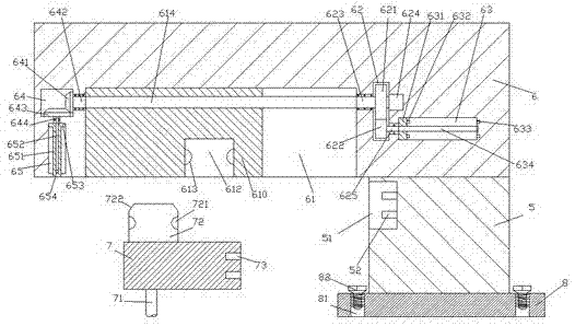
[0023] like Figure 1-Figure 4 As shown, an environmental protection dust removal device of the present invention includes a column body 5, a horizontal frame 6 fixed on the top of the column body 5 and extended to the left, and a plug head 7 mated with the horizontal frame 6, An insertion groove 51 is provided in the left end surface of the cylinder 5, a second insert spring 52 is provided on the right inner wall of the insertion groove 51, and a sliding groove is provided in the bottom end surface of the left extension section of the horizontal frame 6. 61. The sliding groove 61 is provided with a first screw rod 614 extending from left to right, and the screw thread on the first screw rod 614 is connected with a push block 610. The left side of the sliding groove 61 The horizontal frame 6 is provided with a first transmission cavity 64, the horizontal frame 6 below the first transmission cavity 64 is provided with a first sliding cavity 65, and the horizontal frame on the r...


PUM


Abstract

The invention discloses an environment-friendly dust removal device, which comprises a column body, a horizontal frame fixed on the top of the column body and extended to the left, and a plug-in head cooperating with the horizontal frame, and an insertion groove is arranged in the left end surface of the column body , the inner wall on the right side of the insertion groove is provided with a second insertion spring, and the bottom end surface of the extension section on the left side of the horizontal frame is provided with a sliding groove, and a first spiral rod extending left and right is arranged in the sliding groove, and the first spiral rod The upper screw thread is matched with a push block, the horizontal frame on the left side of the sliding groove is provided with a first transmission chamber, the horizontal frame below the first transmission chamber is provided with a first sliding chamber, and the horizontal frame on the right side of the sliding groove The frame is provided with a second transmission cavity, and the second transmission cavity is provided with a first revolving pin shaft extending left and right, and the right end of the first revolving pin shaft is connected to the motor; the invention has a simple structure and can realize automatic control plugging, Automatic control of power supply connection and automatic control of partition extension, high work efficiency and strong safety.

Description

technical field [0001] The invention relates to the technical field of environmental protection dust removal, in particular to an environmental protection dust removal device. Background technique [0002] With the development of the industrial age, people's awareness of environmental protection is increasing. In the production of industrial products, a large amount of dust is generated. Without proper dust removal measures, the environment of the workshop will be polluted and deteriorated, which is harmful to human health. Harmful, the existing dust removal equipment is generally used for industrial dust removal. However, due to the high voltage required for the dust removal equipment to work, although the manual plug-in power supply mode of the existing mid-range is simple, its plug-in stability is poor, and the plug-in Arcs are easy to be generated during the process, and the generation of arcs is likely to cause electric shock to users. It has certain potential dangers t...

Claims


Application Information

Patent Timeline
Patent Type & Authority Applications(China)
IPC IPC(8): H01R13/447H01R13/629H01R13/631H01R13/66
CPCH01R13/62933H01R13/447H01R13/631H01R13/66
Inventor 蔡永强
Owner 福州市汇合兴机械设备有限公司
Why Eureka
Try Eureka