Cable laying device

A technology of cable laying and beams, applied in the direction of cable laying equipment, etc., can solve problems such as difficult cable laying, achieve the effects of improving installation and disassembly efficiency, light weight, and improving installation efficiency

Inactive Publication Date: 2017-06-20
XUCHANG MEETALL CABLE TRAY
View PDF10 Cites 3 Cited by
  • Summary
  • Abstract
  • Description
  • Claims
  • Application Information

AI Technical Summary

Problems solved by technology

[0003] The purpose of the present invention is to provide a cable laying device to solve the problem of difficult cable laying under the condition of narrow laying space

Method used


Image

  • Cable laying device

Examples


Embodiment 1

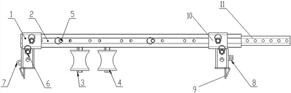
[0024] Such as figure 1 As shown, the cable laying device includes a fixing seat 1 and a beam 2.

[0025] The fixed base 1 includes a main fixed base and a secondary fixed base, the lower ends of the main fixed base and the secondary fixed base are respectively provided with snap-in structures 9, the upper end of the fixed base 1 is provided with mounting holes, and the beam 2 is provided with several positioning holes, The two ends of the crossbeam 2 are installed on two fixed seats respectively, and are fastened by the pull ring indexing pin 6; two pulley assemblies 3 and 4 are installed on the crossbeam, and the binding device can make the cable laying device quickly and stably installed on the On bridges of various widths, the selected standard parts on the market have high versatility;

[0026] A detachable connection structure is provided between the main fixing seat and the secondary fixing seat.

[0027] For better carrying and disassembly, the fixing base is made in...

Embodiment 2

[0031] The beam 2 includes a main beam and a slave beam 11. The main beam adopts a C-shaped steel structure, and the slave beam 11 adopts a square tube structure. The slave beam is nested in the main beam, and a compression spring is arranged between the main beam and the slave beam 11; There are positioning holes 5 on the slave beam, one pulley assembly 3 in the two pulley assemblies is fixed on the main beam, the other pulley assembly 4 is fixed on the slave beam 11, and the two pulley assemblies 3, 4 are on the master and slave beams The position can be adjusted by yourself. The pulley assembly is composed of a square tube and a pulley assembly; the square tube is provided with a row of round holes, which can be adapted to the installation and fixing of cables of various specifications; the pulley is made of nylon material, which is light in weight, good in hardness and flexibility. The groove of the pulley can bear the laying of the largest cable, and the R angle of the ed...

Embodiment 3

[0034] A clasp 9 is provided on the outside of the clamping device, and the connection structure is an automatic binding device whose main body is high-strength nylon. One end of the high-strength nylon is provided with a hook, and the other end is provided with an automatic locking structure.

[0035] When laying cables on site, the two fixing seats are respectively clamped on the two ladder sides of the bridge frame, the hook on the automatic binding device is hung on the clasp outside of one clamping structure, and the automatic locking device is fixed on the other clamping joint. On the clasp on the outside of the structure, the automatic locking device is operated to quickly fix the laying device, improve the installation efficiency and reduce the construction intensity.


PUM


Abstract

The invention discloses a cable laying device. The cable laying device comprises a fixed seat and a cross beam, wherein the fixed seat comprises a main fixed seat and a slave fixed seat, clamping structures are respectively arranged at lower ends of the main fixed seat and the slave fixed seat, two ends of the cross beam are respectively fixed on the two fixed seats, two pulley assemblies are arranged on the cross beam, and a detachable connection structure is arranged between the main fixed seat and the slave fixed seat. With the cable laying device provided by the scheme of the invention, cable laying under a narrow working condition can be met, and the cable laying device is detachable and is convenient to transport and carry.

Description

technical field [0001] The invention belongs to the field of cable laying, in particular to a cable laying device. Background technique [0002] In construction and installation engineering, engineering projects generally use auxiliary devices such as cable laying machines and pulleys in conjunction with manual laying methods for cable laying. 1. The cable laying machine has a large volume, so it cannot be used in the working conditions where the cable laying space is narrow and there are many turns. 2. Pure manual laying is more flexible, and the laying conditions are less restricted, but the labor intensity is high and the efficiency is low. 3. The pulley cable laying is limited by the working height and cannot work in a space with a smaller layer spacing. After the cable is laid, it is necessary to manually pull out the long shaft, lift the cable and take out the pulley; and it can only be used on the straight-through bridge. In the bend bridge. In the nuclear power in...

Claims


Application Information

Patent Timeline
Patent Type & Authority Applications(China)
IPC IPC(8): H02G1/06
CPCH02G1/06
Inventor 尚新春吴杰孙保建李成行王玉玲李鹤鹤王轲
Owner XUCHANG MEETALL CABLE TRAY
Why Eureka
Try Eureka