High-voltage interlocking loop and high-voltage interlocking loop detector

A high-voltage interlock circuit and voltage detector technology, which is applied in the direction of instruments, measuring electronics, and measuring devices, can solve the problems that the diagnostic controller cannot detect the feedback signal and the efficiency of fault detection is low.

Pending Publication Date: 2017-06-23
深圳市瀚路新能源汽车有限公司
View PDF4 Cites 17 Cited by
  • Summary
  • Abstract
  • Description
  • Claims
  • Application Information

AI Technical Summary

Problems solved by technology

[0003] Since the open circuit of the traditional high-voltage interlock circuit occurs, the diagnostic controller cannot detect the feedback signal. It can only simply judge whether the high-voltage interlock circuit is connected, and cannot

Method used


Image

  • High-voltage interlocking loop and high-voltage interlocking loop detector
  • High-voltage interlocking loop and high-voltage interlocking loop detector
  • High-voltage interlocking loop and high-voltage interlocking loop detector

Examples


Embodiment 1

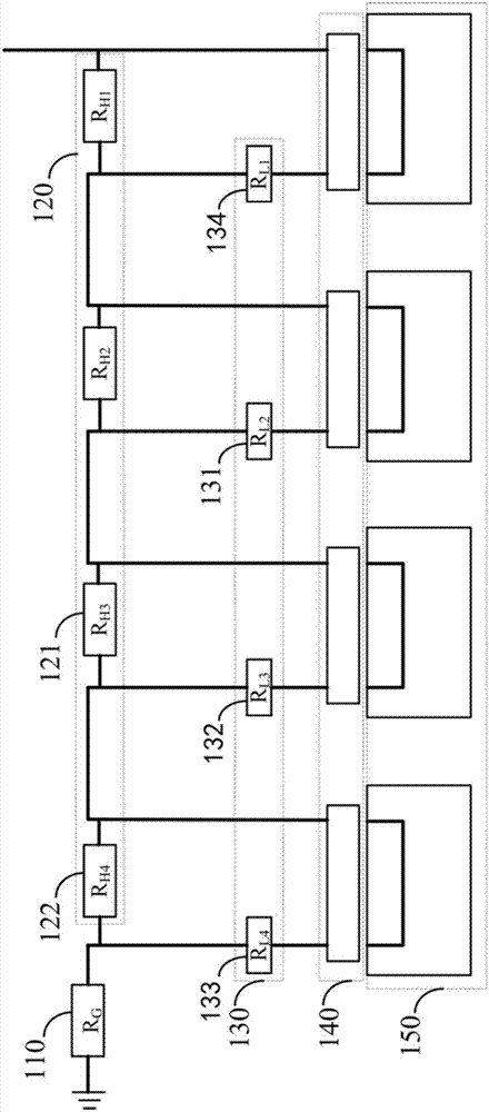
[0049] figure 1 It is a structural diagram of the high-voltage interlock circuit provided by Embodiment 1 of the present invention.

[0050] The high-voltage interlock loop includes: a high-voltage connector 140 and a loop resistor, wherein the loop resistor includes a grounding resistor 110, a low-value resistor 130 and a high-value resistor 120, and the low-value resistor 130 includes a first low-value resistor 131 and a second low-value resistor 132 and a third low-value resistor 133, the high-value resistor 120 includes a first high-value resistor 121 and a second high-value resistor 122;

[0051] The input end of the high-voltage connector 140 is connected with the first low-value resistor 131 and the first high-value resistor 121 respectively, the output end of the high-voltage connector 140 is connected with the second low-value resistor 132, and one end of the grounding resistor 110 is respectively connected with the first low-value resistor 121. The three low-value r...

Embodiment 2

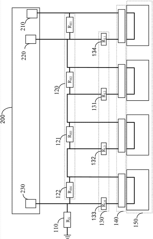
[0058] figure 2 The structure diagram of the high-voltage interlock loop detector provided for the second embodiment of the present invention.

[0059] Exhibit figure 2 , the high-voltage interlock loop detector includes a diagnostic controller 200 and the above-mentioned high-voltage interlock loop, the diagnostic controller 200 is connected with the high-voltage interlock loop, and is used to detect the high-voltage interlock loop, according to the diagnostic signal and the equivalent The resistor obtains voltage information, and diagnoses fault status information according to the voltage information.

[0060] The diagnosis controller 200 includes a signal output controller 210 , a front-end voltage detector 220 and a back-end voltage detector 230 .

[0061] Specifically, the voltage information includes front-end voltage information and back-end voltage information. The signal output controller 210 is connected to the high-voltage connector 140 at the input end of the ...

Embodiment 3

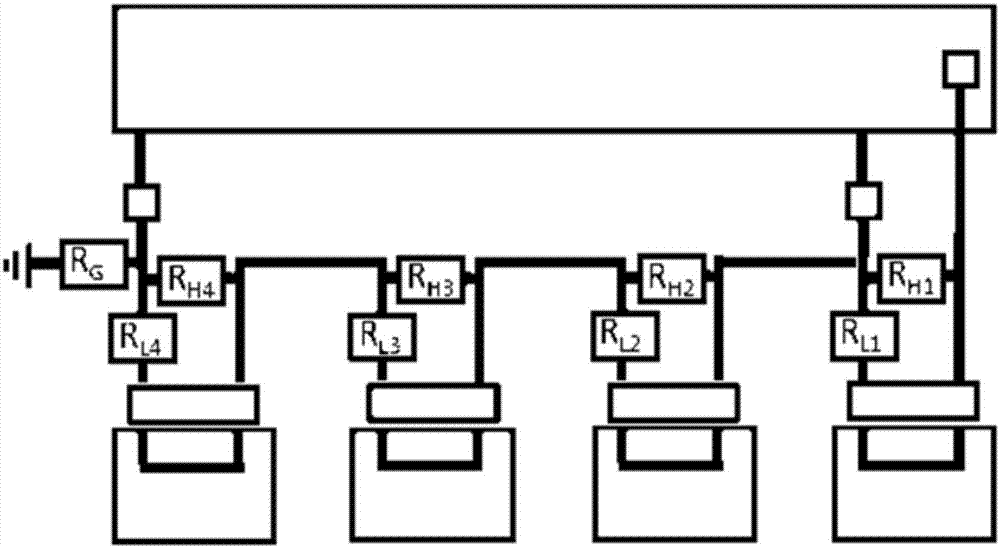
[0066] image 3 The structure diagram of the high-voltage interlock loop detector provided for the third embodiment of the present invention.

[0067] The equivalent resistance includes normal equivalent resistance, the front-end voltage information includes normal front-end voltage information, and the back-end voltage information includes normal back-end voltage information. The front-end voltage detector 220 is also used to detect the front end of the high-voltage interlock circuit, and obtains the normal front-end voltage information according to the diagnostic signal and the normal equivalent resistance; the rear-end voltage detector 230 is also used to detect the rear end of the high-voltage interlock circuit. The end is detected, and the normal back-end voltage information is obtained according to the diagnostic signal and the normal equivalent resistance.

[0068] Specifically, it is assumed that the connection state is that the high-voltage connector 140 is normally ...


PUM


Abstract

The invention provides a high-voltage interlocking loop and a high-voltage interlocking loop detector, and relates to the technical field of high-voltage interlocking loop detection. A diagnosis controller is connected with the high-voltage interlocking loop and used for detecting the high-voltage interlocking loop, obtaining voltage information according to a diagnosis signal and an equivalent resistor and diagnosing fault state information according to the voltage information. The high-voltage interlocking loop is characterized in that the input end of one corresponding high-voltage connector is connected with a first low-value resistor and a first high-value resistor, the output end of the corresponding high-voltage connector is connected with a second low-value resistor, one end of a ground resistor is connected with a third low-value resistor and a second high-value resistor, and the other end of the ground resistor is grounded; the ground resistor, the low-value resistors and the high-value resistors are combined into the equivalent resistor through a loop resistor according to the loop connection state, and external connection with a power supply is achieved through the high-voltage connectors. The state of each high-voltage connector and the fault section of the high-voltage interlocking loop can be judged according to different pieces of voltage information, and the fault detection efficiency can be improved.

Description

technical field [0001] The invention relates to the technical field of detection of a high-voltage interlock circuit, in particular to a high-voltage interlock circuit and a detector for the high-voltage interlock circuit. Background technique [0002] The traditional high-voltage interlock circuit forms a high-voltage interlock circuit through a low-voltage signal line connected in series with high-voltage components through high-voltage connectors. The diagnostic controller outputs a low-voltage diagnostic signal and detects the diagnostic signal at the end of the high-voltage interlock circuit. When the high voltage connector is connected normally, the diagnostic controller can detect the feedback signal, so it can determine that the high voltage interlock circuit is normal. If the high-voltage connector is not connected normally, the high-voltage interlock circuit will form an open circuit. At this time, the diagnostic controller cannot detect the feedback signal, so it ...

Claims


Application Information

Patent Timeline
IPC IPC(8): B60L3/00B60L3/04G01R31/02
CPCB60L3/0023B60L3/04G01R31/50
Inventor 施昌玮黄银大
Owner 深圳市瀚路新能源汽车有限公司
Why Eureka
Try Eureka