
Wireless communication device testability design method

A technology of wireless communication equipment and design method, which is applied in the direction of digital transmission system, electrical components, transmission system, etc., and can solve the problem of poor testability of wireless communication equipment, difficulty in fault diagnosis in the maintenance and support link, single board and complete machine in the production link and other issues to achieve the effect of reducing the difficulty of production commissioning and maintenance and guarantee costs, improving the efficiency of updates and upgrades, and ensuring integrity

Active Publication Date: 2016-05-04
CHONGQING JINMEI COMM
View PDF3 Cites 14 Cited by
  • Summary
  • Abstract
  • Description
  • Claims
  • Application Information

AI Technical Summary

Problems solved by technology

[0005] The purpose of the present invention is to solve the shortcomings of poor testability of wireless communication equipment, inconvenient debugging and testing of single boards and complete machines in the production link, low efficiency, difficult fault diagnosis in the maintenance and support link, and high maintenance and support costs. Therefore, from the perspective of the system A design method for testability of wireless communication equipment is proposed

Method used


Image

  • Wireless communication device testability design method
  • Wireless communication device testability design method

Examples


Embodiment Construction

[0019] The present invention is further described below in conjunction with accompanying drawing, a kind of testability design method of wireless communication equipment, and its method is as follows:

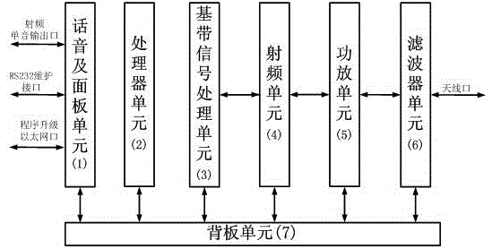
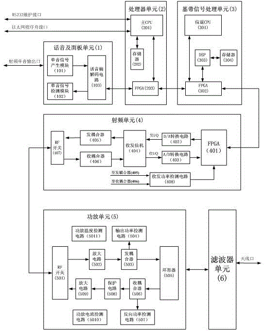
[0020] According to the hardware resources of the equipment, the wireless communication equipment is divided into functional units, including processor unit (1), voice and panel unit (2), baseband signal processing unit (3), radio frequency unit (4), power amplifier unit (5) , filter unit (6) and backplane unit (7), wherein voice and panel unit (1), baseband signal processing unit (3), radio frequency unit (4), power amplifier unit (5), filter unit (6) Connect via the backplane unit (7) and the processor unit (2) through respective control interfaces and data communication interfaces; wherein, the RS232 interface and the Ethernet interface of the processor unit (2) are connected to the voice and panel unit (1 ), install a universal interface connector on the voice and panel uni...


PUM


Abstract

The invention discloses a wireless communication device testability design method. The method includes performing functional unit division on a wireless communication device, including a voice and panel unit, a processor unit, a baseband signal processing unit, a radio frequency unit, a power amplifier unit, a filter unit and a backboard unit, wherein the voice and panel unit, the baseband signal processing unit, the radio frequency unit, the power amplifier unit and the filter unit are connected with the processor unit through respective control interfaces and data communication interfaces via the backboard unit, and the voice and panel unit provides a device internal unit program upgrade interface and maintenance interface to the outside. Main faults of each unit are automatically diagnosed when the device is powered on, a test command is input through the maintenance interface when a fault occurs, a test signal passes through each unit inside and realizes loopback gradually, and the faults of each unit are diagnosed automatically. The wireless communication device testability design method has the beneficial effects of utilizing hardware resources of the device itself, increasing test software to realize testability design of the device itself, accurately positioning the faults inside the device, and greatly reducing debugging and testing and maintenance guarantee cost of the device.

Description

technical field [0001] The invention relates to a testability design method of wireless communication equipment, which belongs to the technical field of testability design of electronic products. Background technique [0002] In the field of digital wireless communication, communication equipment is becoming more and more complex, with higher integration, more powerful functions, and smaller structure size. The corresponding production test and maintenance test are more and more difficult, relying on traditional test methods It has been unable to solve this problem, therefore, it is proposed to increase the testability design requirement while designing the device function. [0003] At present, most products have not been planned for system testability design, and the testability of products is poor. The existing methods usually use boundary scan technology, but this method can only detect chip-level faults for devices with JTAG interface types. The interconnection fault de...

Claims


Application Information

Patent Timeline
IPC IPC(8): H04L12/26H04L12/24
CPCH04L41/0631H04L43/04H04L43/06H04L43/08
Inventor 范朝元肖君苏凌旭胡龙飞
Owner CHONGQING JINMEI COMM
Learn More