Buckling structure of mobile terminal, assembling method, and mobile terminal
A mobile terminal and assembly method technology, applied in the direction of telephone structure, telephone communication, electrical components, etc., can solve the problems of high cost and complex manufacturing process of the buckle structure, and achieve the effect of solving the complex manufacturing process
- Summary
- Abstract
- Description
- Claims
- Application Information
AI Technical Summary
Problems solved by technology
Method used
Image
Examples
Embodiment 1
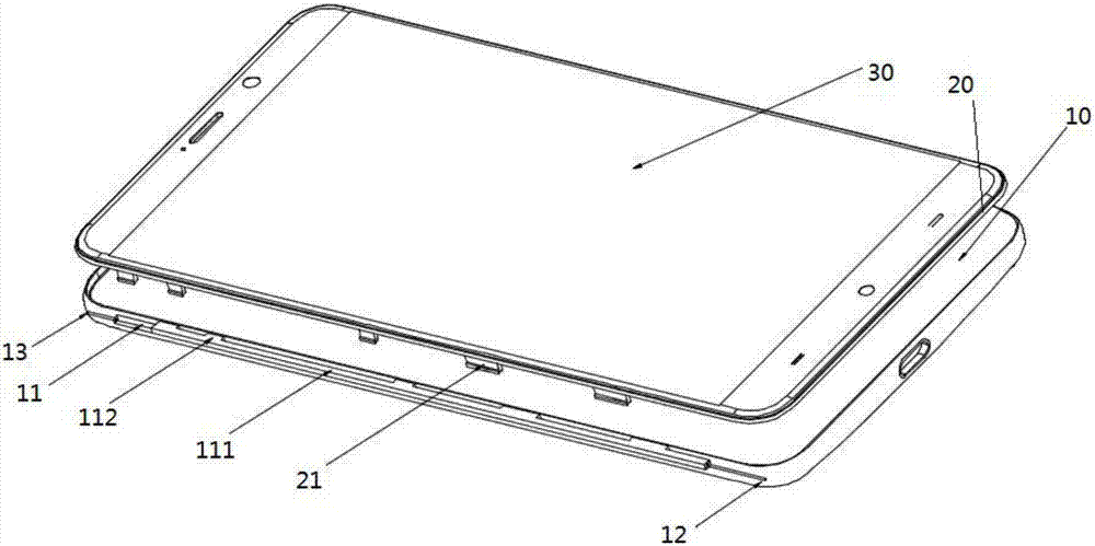
[0039] A fastening structure of a mobile terminal provided by an embodiment of the present invention, such as image 3 As shown, it includes a display screen assembly 30, a middle frame 20, and a rear case 10 for carrying and fixing the middle frame. The middle frame 20 is used for carrying and fixing the display screen assembly 30. The middle frame 20 and the A buckle 21 is provided on the side of the contact surface of the rear shell 10, and a buckle groove 11 is arranged on the inner side of the side wall of the rear shell, and the position of the buckle 21 and the buckle groove 11 correspond to each other, and the inside of the buckle groove 11 A bolt 111 is provided, and a protruding wing 112 is provided on the tether, and the middle frame 20 and the rear case 10 are fixedly connected by the buckle 21 and the protruding wing 112 .
[0040] The fastening structure of the mobile terminal provided in this embodiment is provided with a buckle 21 on the side where the middle f...
Embodiment 2
[0042]On the basis of Embodiment 1, the rear case 10 is provided with a first ejector pin hole 12 and a second ejector pin hole 13, and the first ejector pin hole 12 and the second ejector pin hole 13 are respectively arranged in The bottom case 10 buckles the two ends of the side of the groove 11, and the first thimble hole 12 is used to push one end of the tie bar 111 through the thimble, so that the convex wing 112 on the tie bar 111 is aligned with the middle frame The buckle 21 on 20 is snapped together to realize the fixed connection between the middle frame 20 and the rear case 10; the second thimble hole 13 is used to push the other end opposite to the end of the bolt 111 through the thimble , so that the protruding wings 112 are staggered from the buckle 21 , so that the middle frame 20 is separated from the rear case 10 .
[0043] In this embodiment, a first thimble hole 12 and a second thimble hole 13 are respectively provided on the rear shell 10 at both ends of th...
Embodiment 3
[0047] A method for assembling a fastening structure of a mobile terminal, specifically as Figure 7 As shown, wherein the direction of the rear case 10 pointing to the middle frame 20 is defined as upward, and correspondingly, the direction of the middle frame 20 pointing to the rear case 10 is downward, including:
[0048] S10, attach the middle frame 20 to the bottom case 10, and the buckle 21 and the protruding wing 112 on the bolt 111 are staggered, so that the buckle 21 on the middle frame 20 is placed in the buckle groove 11 on the rear case 10;
[0049] S20 , the thimble pushes one end of the bolt through the first thimble hole 12 , so that the convex wing 112 is engaged with the buckle 21 up and down, so as to realize the fixing of the middle frame 20 and the rear case 10 .
[0050] In the assembly method of the fastening structure of the mobile terminal provided in this embodiment, first, the middle frame 20 is attached to the bottom case 10, and the buckle 21 and th...
PUM
 Abstract
Description
Claims
Application Information
 - R&D
- Intellectual Property
- Life Sciences
- Materials
- Tech Scout
- Unparalleled Data Quality
- Higher Quality Content
- 60% Fewer Hallucinations
Browse by: Latest US Patents, China's latest patents, Technical Efficacy Thesaurus, Application Domain, Technology Topic, Popular Technical Reports.
© 2025 PatSnap. All rights reserved.Legal|Privacy policy|Modern Slavery Act Transparency Statement|Sitemap|About US| Contact US: help@patsnap.com


