Check patentability & draft patents in minutes with Patsnap Eureka AI!

Vacuum cleaner, in particular a hand-held battery cleaner

A vacuum cleaner and hand-held technology, applied in the field of hand-held battery vacuum cleaners, can solve the problem of clogging the opening of the suction chamber by the suction, and achieve the effect of eliminating the clogging

Inactive Publication Date: 2017-06-27
VORWERK & CO INTERHOLDING GMBH
View PDF5 Cites 1 Cited by
  • Summary
  • Abstract
  • Description
  • Claims
  • Application Information

AI Technical Summary

Problems solved by technology

The disadvantage here is that the cross-section of the suction chamber is generally larger than the cross-section of the opening of the suction chamber, so that suction or blowing often results in the opening of the suction chamber being blocked by the suction

Method used


Image

  • Vacuum cleaner, in particular a hand-held battery cleaner
  • Vacuum cleaner, in particular a hand-held battery cleaner
  • Vacuum cleaner, in particular a hand-held battery cleaner

Examples


Embodiment Construction

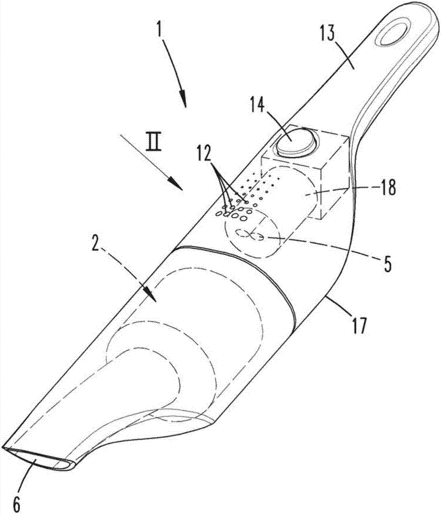
[0025] figure 1A vacuum cleaner 1 is shown, which is designed here as a hand-held battery vacuum cleaner. The vacuum cleaner 1 has a housing 17 with a suction opening 6 for suction to enter the suction chamber 2 of the vacuum cleaner 1 . The vacuum cleaner 1 has a fan 5 which is driven by means of an electric motor 18 . When the blower 5 is in operation, suction is sucked into the suction chamber 2 through the suction opening 6 . With filter element 7 (see figure 2 ) clean air reaches the fan 5 and is then discharged through the outlet opening 12 of the housing 17 into the environment outside the vacuum cleaner 1 . The housing 17 of the vacuum cleaner 1 also has a switch 14 , which is designed here as an activation and deactivation switch, and a handle 13 for operating the vacuum cleaner 1 by the user.

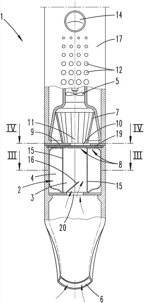
[0026] figure 2 The vacuum cleaner 1 is shown partially exposed. Starting from the suction opening 6 , a suction chamber 2 is firstly arranged inside the vacuum cleane...


PUM


Abstract

The invention relates to a vacuum cleaner (1), in particular a hand - held battery cleaner, comprising a suction chamber (2) and a blower (5) for conveying suction - laden air through a suction opening (6) of the vacuum cleaner (1) into the suction space (2). In order to make possible a trouble - free regeneration of the suction space (2) and to optimize the suction operation, it is proposed that the suction space (2) has a plurality of suction chambers (3, 4), to which an orifice (9) with at least one orifice opening (10) is assigned, wherein the suction chambers (3, 4) and / or the diaphragm (9) are displaceable in such a way that the diaphragm opening (10) is assigned alternately only to a single suction chamber (3, 4) or a part of the suction chambers (3, 4).

Description

technical field [0001] The invention relates to a vacuum cleaner, especially a hand-held battery vacuum cleaner, which has a suction chamber and a fan for conveying air loaded with suction into the suction chamber through a suction opening of the vacuum cleaner. Background technique [0002] Vacuum cleaners of the above-mentioned kind have been sufficiently disclosed. During the suction operation of the vacuum cleaner, the suction material is transported from the surface to be cleaned into the suction material chamber by means of a fan, wherein the suction material contained in the conveyed air is contained in the suction material chamber, especially in the Deposits are deposited on the filter elements of the chamber so that only cleaned air reaches the fan. In this case, the suction chamber can either be designed reproducibly or have a disposable filter, for example a conventional dust filter bag. [0003] In the case of a regenerable suction chamber, the suction chamber ...

Claims


Application Information

Patent Timeline
IPC IPC(8): A47L5/14A47L9/10
CPCA47L5/14A47L9/10A47L5/24A47L9/102A47L9/20
Inventor M.科内利森
Owner VORWERK & CO INTERHOLDING GMBH
Features
  • R&D
  • Intellectual Property
  • Life Sciences
  • Materials
  • Tech Scout
  • Unparalleled Data Quality
  • Higher Quality Content
  • 60% Fewer Hallucinations
Learn More