Surface polishing apparatus including a dresser

a surface polishing and dresser technology, applied in the direction of lapping machines, manufacturing tools, abrasive surface conditioning devices, etc., can solve the problems of increasing the running cost, deteriorating the polishing rate, and fluctuating the amount of polishing for each workpiece,

Inactive Publication Date: 2000-03-21
NEC CORP
View PDF6 Cites 21 Cited by
  • Summary
  • Abstract
  • Description
  • Claims
  • Application Information

AI Technical Summary

Problems solved by technology

The above-mentioned conventional polishing apparatus, however, generates clogging in the processing surface as time passes in polishing, resulting in a deterioration in the polishing rate (ie., amount of polishing/time) and fluctuations in the amount of polishing for each work piece.
Moreover, the abrasive slurry has to be drained each time a work piece is polished, increasing the

Method used


Image

  • Surface polishing apparatus including a dresser
  • Surface polishing apparatus including a dresser
  • Surface polishing apparatus including a dresser

Examples


first embodiment

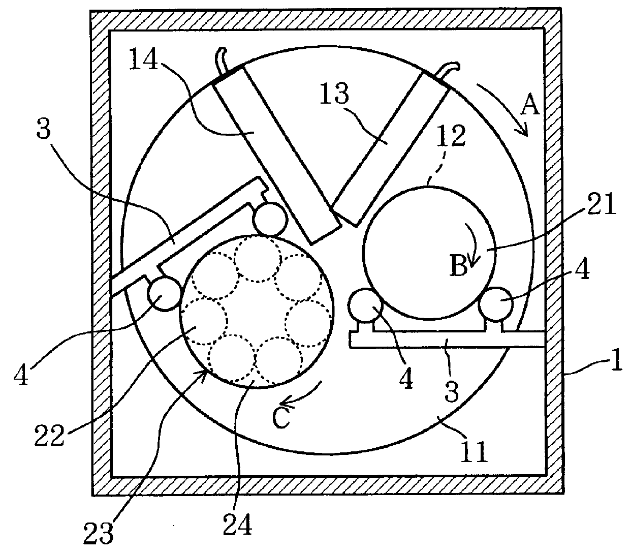
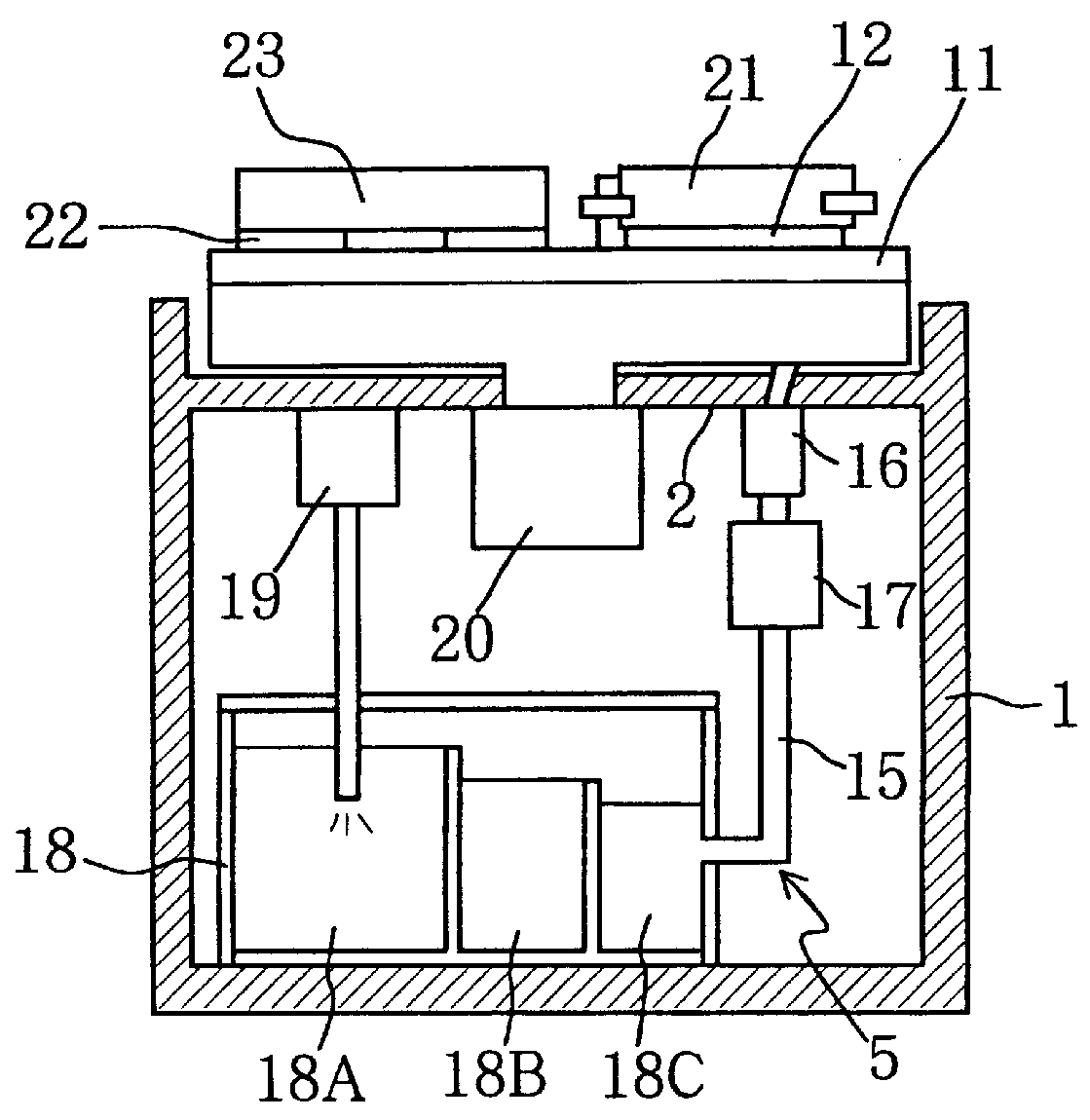
FIG. 1 is a plan view of a surface polishing apparatus of the present invention, while FIG. 2 is its side view. As shown in these figures, an upper frame 2 of a frame 1 of the surface polishing apparatus is mounted thereon with a rotational disk-shaped polishing tool 11 with its processing surface facing upward. The polishing tool 11 is driven and rotated in a direction of an arrow A (clockwise as viewed from the top) by a motor 20.

A work piece 12 is pressed into contact with the processing surface of the polishing tool 11 by a pressure-application retainer plate 21. The pressure-application retainer plate 21 is on the work piece 12, which is in turn on the processing surface of the polishing tool 11. Therefore, both the pressure-application retainer plate 21 and the work piece 12 are held at the home position so that they can be rotated on their own axes, by a pair of support rollers of a horizontal frame 3 arranged on the forward side of the work piece 11 as against the rotation d...

second embodiment

Now, the second embodiment of the present invention is described below.

FIG. 5 is a plan view of a surface polishing apparatus according to the second embodiment of the present invention, while FIG. 6 is its side view. In the surface polishing apparatus according to the second embodiment, during polishing, two work pieces 12 are placed about the rotation center of a polishing tool 11 (FIG. 5).

Therefore, each of two box-shaped abrasive slurry-supply mechanisms 13 is arranged on the backward side in rotation of each of the two work pieces 12, while each of two box-shaped abrasive slurry-suction mechanisms 14 is arranged on the forward side of each of the two work pieces 12. Also, each of two dresser 27 is arranged between each box-shaped abrasive slurry-suction mechanism 14 and each work piece 12. As the dressers 27, cylinder-shaped diamond grindstones (roller-shaped grindstones) are employed for compacting. The other features of structure are the same as the first embodiment.

The dress...


PUM


Abstract

A surface polishing apparatus which presses a work piece 12 into contact with the processing surface of a disk-shaped polishing tool 11 which is rotated and driven, to polish the surface of the work piece 12 as supplying abrasive slurry to the processing surface. The surface polishing apparatus includes an abrasive slurry-supply mechanism 13 which supplies abrasive slurry to the processing surface. The slurry supply mechanism is provided on the backward side of the work piece with respect to the rotation direction of the polishing tool. A dresser 23, which sets the processing surface, is provided on the forward side of the work piece an abrasive slurry-suction mechanism, which sucks and recycles abrasive slurry from the processing surface, is provided on the forward side of the dresser and on the backward side of abrasive slurry-supply mechanism 13.

Description

1. Field of the InventionThe present invention relates to a surface polishing apparatus for highly smoothly polishing the surfaces of semiconductor wafers, wafers with semiconductor-IC covered with insulator films, wafers with metal wirings, magnetic disks, glass substrates, and other plate-shaped work pieces.2. Description of the Related ArtRecently, surface polishing apparatuses described in Japanese Patent Laid-open Publication Nos. Hei4-33336, Hei5-69310, and Hei5-309559 have been utilized to polish semiconductor wafers, magnetic disks, etc.FIG. 8 shows an example of the conventional surface polishing apparatuses similar to that in the above-mentioned patent publications. The present surface polishing apparatus presses a work piece 132, using a pressure-retainer plate 133, into contact with the upward processing surface of a disk-shaped polishing tool 131 which is driven rotationally, to polish the surface of the work piece 132 as supplying abrasive slurry 134 to the processing ...

Claims


Application Information

Patent Timeline
IPC IPC(8): B24B53/007B24B37/04B24B57/00B24B57/02B24B37/00B24B53/017
CPCB24B53/017B24B57/02
Inventor MITSUHASHI, MASASHIGEOHNO, KENICHIYOSHIDA, KENICHI
Owner NEC CORP
Why Eureka
Try Eureka