Exercise device

The technology of a sports device and an elastic device is applied in the directions of sports accessories, training equipment for adjusting the cardiovascular system, training equipment for adjusting coordination, etc., and can solve the problems of insufficient thrust and difficulty in simulating stepping and striding.

Inactive Publication Date: 2017-06-27
DYACO INT INC
10 Cites 3 Cited by

AI-Extracted Technical Summary

Problems solved by technology

In the above-mentioned structure, the thrust of pedal ascending is insufficient,...

Method used

With reference to Fig. 2 to Fig. 5, sports device 1 can also have handrail 19, and handrail 19 is held by t...

Abstract

The invention discloses an exercise device comprising a framework, two swing tubes, two foot pedal tubes, two pedals, a resistance device, two transmission assemblies and two sliding tubes. Two swing tubes are arranged at a left side and a right side of the framework; a first end of each swing tube is connected to the framework in a pivoted mode; the two foot pedal tubes are respectively connected to the two swing tubes; a first end of each foot pedal tube is connected to a second end of the corresponding swing tube in a pivoted mode; two pedals are respectively connected with the two food pedal tubes; each pedal is connected to a second end of the corresponding foot pedal tube. The resistance device provides operation resistance. The two transmission assemblies are respectively arranged at two sides of the resistance device; a first end of each transmission assembly is connected to the framework and the second end is connected to a corresponding foot pedal tube; two sliding tubes are fixed to the framework and are slidingly connected with two foot pedal tubes. By means of the invention, the motion locus of two pedals is arc line whose center slightly points to a certain portion of a user, such as shanks or feet, wherein the motion locus accords with human body ergonomics.

Application Domain

Movement coordination devicesMuscle exercising devices +1

Technology Topic

Physical exerciseEngineering

Image

  • Exercise device
  • Exercise device
  • Exercise device

Examples

  • Experimental program(1)

Example Embodiment

[0051] The embodiments of this case will be described in detail below, and the drawings will be used as examples. In some embodiments, the examples shown in the figures may be to scale, but in other embodiments, it is not necessary to scale. In some embodiments, the same or similar component symbols may represent the same, similar, or simulated components and/or elements, but in some embodiments, they may also represent different components. In some embodiments, nouns describing directions, such as up, down, left, right, up, down, over, above, below, back, front, etc., can be interpreted literally, but in other embodiments, It can be interpreted without literal meaning. In addition, in order to clearly indicate certain components of the present invention, some components may be omitted from the icons. In the description of the specification, in order to enable the reader to have a more complete understanding of the present invention, many specific details are provided; however, the present invention may still be implemented under the premise that some or all of these specific details are omitted.
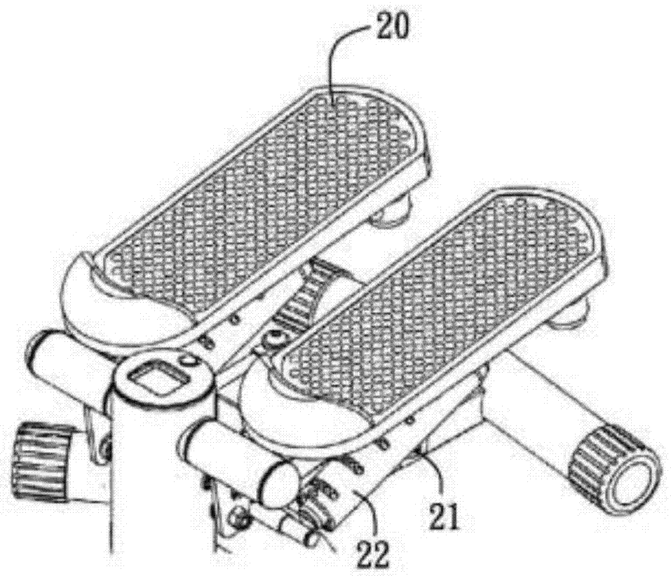
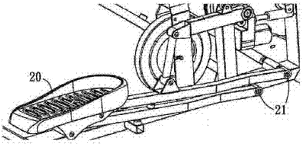
[0052] figure 2 with image 3 Is a three-dimensional view, Figure 4 with Figure 5 It is a side view showing the exercise device 1 of the preferred embodiment of the present invention. reference Figure 2 to Figure 4 , The exercise device 1 includes a skeleton 10, two swing tubes 11, two pedal tubes 12, a resistance device 13, a variable ratio device 14, two transmission components 15, two pedals 16, two roller sets 17, two sliding Tube 18.
[0053] reference Figure 2 to Figure 5 In this embodiment, the skeleton 10 includes, but is not limited to, a base 101 and a main frame 102. The base 101 is located on the supporting surface or the ground, and the main frame 102 is located above the base 101. As an illustration and not a limitation, there is a standpipe 103 above the main frame 102, and one end of the standpipe 103 is connected to the main frame 102, and the other end may have an operating interface (not shown in the figure) for user operation or control.
[0054] reference Figure 2 to Figure 5 The above-mentioned two swing tubes 11 are respectively located on the left and right sides of the frame 10, and the first end of each swing tube 11 is pivotally connected to the frame 10 on the shaft 1022. The two foot tubes 12 are respectively connected to the two swing tubes 11, and the first end of each foot tube 12 is pivotally connected to the second end of the corresponding swing tube 11. The two pedals 16 are respectively connected to the two foot tubes 12, and each pedal 16 is connected to the second end of the corresponding foot tube 12.
[0055] reference Figure 2 to Figure 5 , The two transmission components 15 are located on both sides of the resistance device 13 respectively. The resistance device 13 has an axis (not shown in the figure) and provides operation resistance. The two transmission components 15 are respectively connected to a foot tube 12, and the resistance device 13 is connected through the ratio changing device 14. In this embodiment, each transmission component 15 may include, but is not limited to, an elastic device 150, a timing belt 152, and a timing gear 154. Among them, the elastic device 150 is preferably a spring, with a first end connected to the frame 10 (for example, connected to the main frame 102 of the frame 10), a second end connected to the first end of the timing belt 152, and the first end of the timing belt 152 A foot tube 12 is connected to the two ends, for example, a part of the foot tube 12 between the first end and the second end is connected. In addition, a part of the timing belt 152 meshes with the timing gear 154. In addition, the timing belt 152 can bypass one or more pulleys. For example, the timing belt 152 bypasses the first pulley 156 provided on the base 101, and then bypasses the timing gear 154 and connects to a foot tube 12.
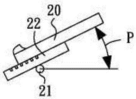
[0056] reference Figure 2 to Figure 5 , The two sliding pipes 18 are respectively located on both sides of the frame 10 and connected with the frame 10 respectively. For example, the first end of each sliding tube 18 is connected to the main frame 102, and the second end of each sliding tube is connected to the base 101. In addition, in this preferred embodiment, the exercise device 1 further includes two roller sets 17, each roller set 17 includes a front wheel 172 and a rear wheel 174, wherein the central axis of the front wheel 172 and the central axis of the rear wheel 174 Connect a foot tube 12. The front wheel 172 and the rear wheel 174 can be respectively located at the front and rear of a sliding tube 18, and the rear wheel 174 has a groove in the shape of the sliding tube 18, so that the rear wheel 174 abuts against the sliding tube 18, and the front wheel 172 does not contact the sliding tube 18, but the movement of the foot tube 16 can be restricted to move along the sliding tube 16. Each roller set 17 may also include a fixing mechanism (not shown in the figure) to fix the front wheel 172 and the rear wheel 174. The size of the rear wheel 174 may be larger than the front wheel 172. With the above structure, the pedal 16 is restricted from moving between the upper end and the lower end of the sliding tube 18 along the arc profile. Figure 4 The display roller set 17 drives the pedal 16 to make an arc-shaped movement track P. Such as Figure 4 As shown, when the pedal 16 moves to a high point, its angle is relatively inclined; Figure 5 As shown, when the pedal 16 moves to a low point, its angle is slightly forward or close to horizontal, which conforms to the ergonomics of stepping, stepping, or mountaineering, so that the operator will not feel discomfort. According to the roller set 17 of the preferred embodiment of the present invention, the stability of the pedal 16 during movement can be improved. When the speed of the pedal 16 increases, the sliding tube 18 will not be separated.
[0057] reference Figure 2 to Figure 5 In this preferred embodiment, the two transmission components 15 are connected to the resistance device 13 through a ratio changing device 14. In this preferred embodiment, the resistance device 13 is used to provide resistance, and may include, but is not limited to, a belt pulley 132 and a flywheel 134, which may be connected by a connecting member (such as a belt). The variable ratio device 14 may include, but is not limited to, a large wheel 140 and a small wheel 142. The large wheel 140 may be arranged on the main frame 102. The large wheel 140 and the small wheel 142 are connected by a transmission member (such as a belt). The resistance device 13 is connected by a bearing (not shown in the figure), and the two timing gears 154 are axially connected with the big wheel 140 by a one-way bearing (not shown in the figure). Thus, when the user stands on the pedal 16 and applies force to move the pedal 16 down along the sliding tube 18, the timing belt 152 drives the timing gear 154 to rotate, the timing gear 154 drives the big wheel 140 to rotate, and the big wheel 140 The small wheel 142 and the pulley 132 are driven to rotate, and the pulley 132 drives the flywheel 134 to rotate. When the user does not apply force, the elastic device 150 can pull the pedal 16 upward through the timing belt 152 so that the pedal 16 moves upward along the sliding tube 18. At this time, the timing gear 154 will not drive the big wheel 140 to rotate.
[0058] In this preferred embodiment, the timing gears 154 of the two transmission assemblies 15 are connected to the resistance device 13 through a ratio changing device 14. In other embodiments of the present invention, the timing gears 154 of the two transmission components 15 can also be directly connected to the pulley 132 of the resistance device 132 through a one-way bearing (not shown in the figure). That is, the variable ratio device 14 can be omitted.
[0059] Since the resistance device 13 has a transmission assembly 15 on each side, and a foot tube 12 is connected respectively. Therefore, unlike the prior art that connects the resistance device 13 through two cranks, the two pedals 16 can be operated independently. That is, the two pedals 16 can be simultaneously forced to move down along the corresponding sliding tube 18, or simultaneously pulled up by the corresponding transmission assembly 15 and moved up along the corresponding sliding tube 18 at the same time. Alternatively, the two pedals 16 can perform relative movement up and down.
[0060] reference Figure 2 to Figure 5 The exercise device 1 may also have an armrest 19 for the user to hold, which can increase the safety in use and facilitate the user to stand on the pedal 16 or leave from the pedal 16.
[0061] Image 6 with Figure 7 Is a three-dimensional view, Picture 8 with Picture 9 It is a side view showing the exercise device 2 according to another embodiment of the present invention. The exercise device 2 has similar features to the exercise device 1, the only difference is that in the foregoing embodiment, the elastic device of the transmission assembly 15 is a spring, while in this embodiment, the elastic device 150 is a bungee cord. In addition, the transmission assembly also includes a second pulley 158. The first end of the elastic device 150 is fixed to the main frame 102. In addition, the elastic device 150 bypasses the second pulley 158 provided on the main frame 102 and then bypasses the first pulley provided on the base 101 to connect the first end of the timing belt 152 with the second end. The other features of this embodiment are the same as the previous embodiments, and will not be described again.
[0062] For each/all embodiments disclosed in this specification, those skilled in the art can make various modifications, changes, combinations, exchanges, omissions, substitutions, and equivalent changes accordingly. As long as they are not mutually exclusive, they belong to the present invention. The concept belongs to the scope of the present invention. The structures or methods that can correspond to or are related to the features of the embodiments described in this case, and/or any applications, abandoned, or approved applications of the inventor or assignee, are all incorporated herein and regarded as part of the description of this case. The incorporated part includes part or all of its correspondence, correlation and modification, (1) operable and/or constructible (2) modified to be operable and/or constructable according to those skilled in the art (3) Implementation/manufacture/use or combination of the specification of this case, related applications of this case, and any part based on the common sense and judgment of those skilled in the art.
[0063] Unless otherwise specified, some conditional sentences or words, such as "can", "could", "may", or "may", usually try to express that the embodiment of this case has, But it can also be interpreted as features, components, or steps that may not be needed. In other embodiments, these features, components, or steps may not be needed.
[0064] The contents of the aforementioned documents in this article are all incorporated into this article and regarded as part of the specification of this case. The embodiments provided in the present invention are merely illustrative, and are not intended to limit the scope of the present invention. The features or other features mentioned in the present invention include method steps and technologies, and can be combined or changed in any way with the features or structures described in the related application. Part or all of them can be regarded as unequal and separate from the present application. , Irreplaceable embodiment. The features and methods disclosed in the present invention correspond to or are related, including those that can be derived from the text and are not mutually exclusive, and those that are modified by those skilled in the art, some or all of which may be (1) operable and/ Or constructible (2) Modified to be operable and/or constructable based on the knowledge of those skilled in the art (3) Implement/manufacture/use or combine with any part of the specification of the case, including (I) the present invention or related Any one or more parts of the structure and method, and/or (II) any one or more inventive concepts of the present invention and any changes and/or combinations of the contents of the parts thereof, including any one or more features Or any modification and/or combination of the content of the embodiment.

PUM

no PUM

Description & Claims & Application Information

We can also present the details of the Description, Claims and Application information to help users get a comprehensive understanding of the technical details of the patent, such as background art, summary of invention, brief description of drawings, description of embodiments, and other original content. On the other hand, users can also determine the specific scope of protection of the technology through the list of claims; as well as understand the changes in the life cycle of the technology with the presentation of the patent timeline. Login to view more.
Why Eureka
Try Eureka