Toilet cleaning system

A technology for cleaning systems and toilets, applied to indoor sanitary pipeline installations, sanitary equipment for toilets, floors, etc., can solve the problems of poor ventilation in exhaust systems, slippery floors, and high costs, and achieve improved cleanliness, Good adsorption effect

Pending Publication Date: 2017-06-27
河南蚁巢科技有限公司
View PDF10 Cites 1 Cited by
  • Summary
  • Abstract
  • Description
  • Claims
  • Application Information

AI Technical Summary

Problems solved by technology

[0002] Along with the country's continuous emphasis on environmental sanitation, the investment in public toilets also continues to rise, such as highway toilets, some important public exhibition hall toilets, and public toilets in large companies; toilet cleaning involves ventilation and cleaning, prior art Among them, it can be solved by installing an exhaust system in the ceiling of the bathroom, and the ventilation effect of the exhaust system is poor; in addition, the cleaning is basically solved by manual work, the cost is getting higher and higher, and when the manual cleans the toilet, it is necessary to clean the urinal and the ground, when cleaning the ground, one is that the efficiency of cleaning the ground is not high, and the other is that the ground after cleaning is slippery

Method used


Image

  • Toilet cleaning system
  • Toilet cleaning system
  • Toilet cleaning system

Examples


no. 1 example

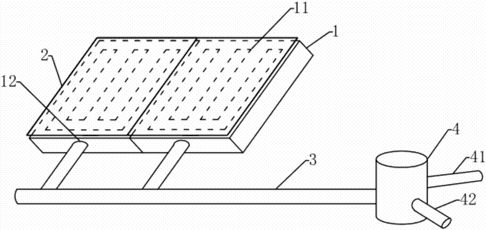
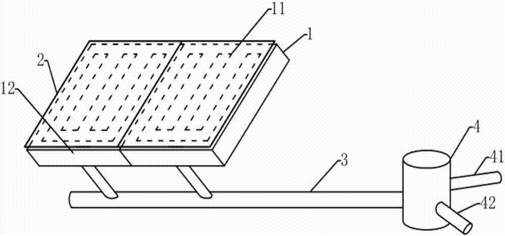
[0016] The first embodiment, such as figure 1 As shown, a toilet cleaning system includes two planks, a filter cloth and a vacuum pump water vapor separator, and a drainage groove is provided in the upper end surface of the plank, where three parallel strip drainage grooves are provided on the plank, The lower ends of the three drainage grooves are connected to the horizontal drainage grooves, and an air extraction hole is provided on the side outer wall of the plank, the inner end port of the air extraction hole communicates with the horizontal drainage groove, and the outer end port of the air extraction hole passes through After the total exhaust pipe is communicated with the inlet of the vacuum pump water vapor separator; the filter cloth is laid on the upper surface of the plank, and the edge of the filter cloth is sealed and connected with the edge of the plank. There is a card slot on the edge of the plank, and through the cooperation of the seal and the card slot, the ...

no. 3 example

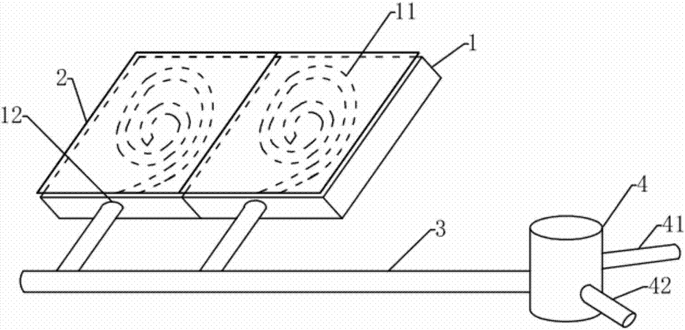
[0020] The third embodiment, other technical features are the same as the first embodiment, the drainage groove starts from the center point of the plank and extends outward in a spiral shape, and communicates with the air suction hole when extending to the edge of the plank In this way, the covered area of ​​the gutter is relatively large, and the structure of the plank is relatively stable and not easily damaged.

[0021] In addition, no matter it is the first embodiment, the second embodiment or the third embodiment, when the width of the drainage groove is set larger, a supporting grid is installed in the drainage groove, so that the supporting grid is in the drainage groove. Support the filter cloth to prevent the filter cloth above the drain tank from being stepped on and sink into the drain tank, or affect the connection between the filter cloth and the edge of the deck, so as to maintain the flatness of the filter cloth.

[0022] The beneficial effect of the present in...


PUM


Abstract

The invention relates to the field of public toilet cleaning, in particular to a toilet cleaning system, comprising flat plates, filter cloth, and an evacuating pump water-vapor separator; a drain channel is arranged in the upper end face of each flat plate; the outer wall of each flat plate is provided with an evacuating hole; an inner opening of each evacuating hole is communicated with one end of the corresponding drain channel, and an outer opening of each evacuating hole is communicated with an inlet of the evacuating pump water-vapor separator; the filter cloth is laid on the upper end faces of the flat plates, and the edges of the filter cloth are hermetically connected to the edges of the flat plates. The filter cloth easy to dry and wash is laid herein and is evacuated while a toilet is exhausted; in this way, cleaning and exhausting of the toilet are combined, and the public toilet has improved cleanliness, dryness, air freshness and floor slip resistance; the flat plates provided herein are modularly arranged such that it is convenient to splice and lay in specific positions; the filter cloth used herein can well adsorb fouling, and can be cleaned just by direct flushing.

Description

technical field [0001] The invention relates to the field of public toilet cleaning, in particular to a toilet cleaning system. Background technique [0002] Along with the country's continuous emphasis on environmental sanitation, the investment in public toilets also continues to rise, such as highway toilets, some important public exhibition hall toilets, and public toilets in large companies; toilet cleaning involves ventilation and cleaning, prior art Among them, it can be solved by installing an exhaust system in the ceiling of the bathroom, and the ventilation effect of the exhaust system is poor; in addition, the cleaning is basically solved by manual work, the cost is getting higher and higher, and when the manual cleans the toilet, it is necessary to clean the urinal And the ground, when cleaning the ground, one is that the efficiency of cleaning the ground is not high, and the other is that the ground after cleaning is slippery. Contents of the invention [000...

Claims


Application Information

Patent Timeline
Patent Type & Authority Applications(China)
IPC IPC(8): E03D9/04E04F15/16E03C1/12
CPCE03C1/12E03D9/04E04F15/163
Inventor 沙慧芳田金新
Owner 河南蚁巢科技有限公司
Why Eureka
Try Eureka