
Energy adjustment system

An energy adjustment and displacement technology, applied in fluid transmission, belt/chain/gear, mechanical equipment, etc., can solve problems such as low efficiency, occupying effective space, increasing weight, etc., achieving simple structure, good load response, and convenience. Kinetic energy regeneration and the effect of the drivetrain

Inactive Publication Date: 2017-06-27
ENTROPY ZERO TECH LOGIC ENG GRP CO LTD
View PDF4 Cites 0 Cited by
  • Summary
  • Abstract
  • Description
  • Claims
  • Application Information

AI Technical Summary

Problems solved by technology

[0002] Motion systems with fast load changes, such as vehicles and tanks, often need to configure engines according to the highest load requirements due to the need to meet high load requirements, so that they are in the state of large horses and small carts most of the time, which not only occupies a large number of effective Space, adding a lot of weight, also causing serious inefficiency and energy waste, at the same time, if the braking energy of this type of system can be used, the efficiency can be improved

Method used


Image

  • Energy adjustment system
  • Energy adjustment system
  • Energy adjustment system

Examples


Embodiment 1

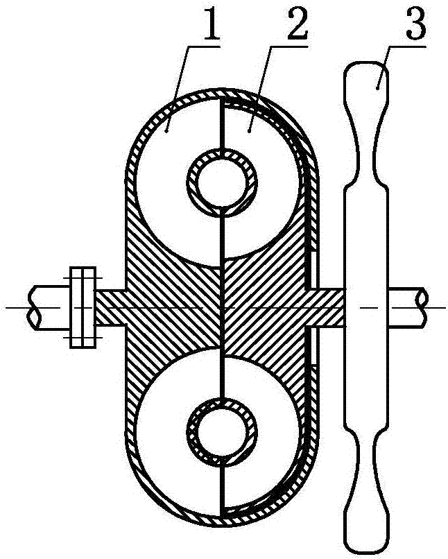
[0029] An energy regulation system such as Figure 1.1 and 1.2 As shown, it includes a pump wheel 1 and a turbine 2, the pump wheel 1 and the turbine 2 are connected in series, the turbine 2 is mechanically connected to the rotating inertia body 3, and the working medium of the pump wheel 1 and the turbine 2 Either as a gas or as a gas-liquid two-phase mixture.

Embodiment 2

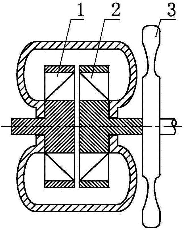
[0031] An energy regulation system such as Figure 2.1 and 2.2 As shown, the pump wheel 1 and the turbine wheel 2 are included, the pump wheel 1 and the turbine wheel 2 are connected in series, the turbine wheel 2 is increased in weight, and the working medium of the pump wheel 1 and the turbine wheel 2 is set as gas or It is a gas-liquid two-phase mixture.

Embodiment 3

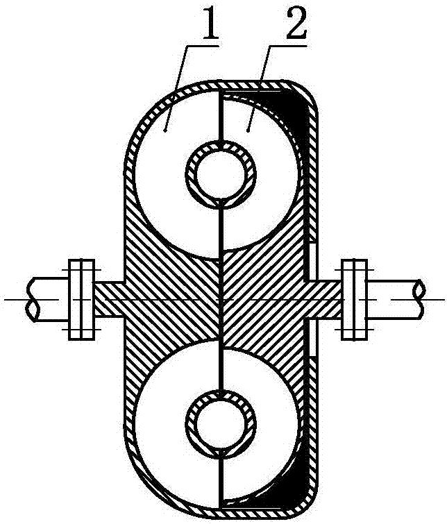
[0033] An energy regulation system such as Figure 3.1 and 3.2 As shown, the pump wheel 1 and the turbine wheel 2 are included, and the pump wheel 1 and the turbine wheel 2 are connected in series. 1 and the working medium of the turbine 2 are set as gas or as a gas-liquid two-phase mixture.


PUM


Abstract

The invention discloses an energy adjustment system. The energy adjustment system comprises a pump wheel and a turbine. The pump wheel and the turbine are correspondingly arranged. The turbine is arranged in a weight increase manner, and / or the turbine and a rotary inertia body are mechanically arranged. A working medium of the pump wheel and the turbine is liquid or gas or a gas-liquid two-phase mixture. The energy adjustment system is good in load response, simple in structure and capable of conveniently achieving kinetic energy regeneration and optimization of a transmission system.

Description

technical field [0001] The invention relates to the field of power and transmission, in particular to an energy adjustment system. Background technique [0002] Motion systems with fast load changes, such as vehicles and tanks, often need to configure engines according to the highest load requirements due to the need to meet high load requirements, so that they are in the state of large horses and small carts most of the time, which not only occupies a large number of effective Space, adding a lot of weight, also causing serious inefficiency and energy waste, at the same time, if the braking energy of this type of system can be used, the efficiency can be improved. In addition, using impeller fluid mechanisms such as torque converters and couplers and flywheels (rotating inertia bodies) to quickly store and release kinetic energy can solve the load response and energy-saving and environmental protection problems of the power system. Therefore, it is necessary to invent a no...

Claims


Application Information

Patent Timeline
Patent Type & Authority Applications(China)
IPC IPC(8): F16H41/04F16H41/32F16H47/06
CPCF16H41/04F16H41/32F16H47/06
Inventor 靳北彪
Owner ENTROPY ZERO TECH LOGIC ENG GRP CO LTD
Learn More