Power system
A power system and power shaft technology, applied in the direction of transmission, fluid transmission, belt/chain/gear, etc., can solve the problem of affecting system noise, vibration life and efficiency, unfavorable prime mover power shaft torque distribution, and affecting system pollution emissions and other problems, to achieve the effect of simple structure, good environmental performance and good load response
- Summary
- Abstract
- Description
- Claims
- Application Information
AI Technical Summary
Problems solved by technology
Method used
Image
Examples
Embodiment 1
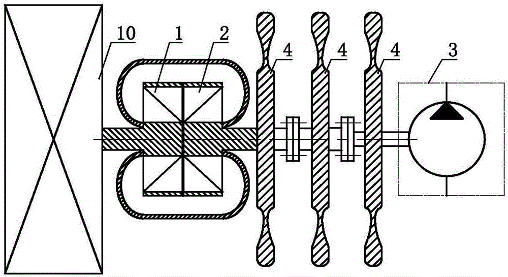
[0038] a power system such as Figure 1.1 and 1.2 As shown, it includes an engine 10, an impeller A1 and an impeller B2, the engine 10 is set in transmission with the impeller A1, the impeller A1 and the impeller B2 are connected in series, and the impeller B2 is connected to the hydraulic pressure The pump 3 is set in transmission, and the inertia body 4 is arranged on the impeller B 2 , on the transmission member between the impeller B 2 and the hydraulic pump 3 , and on the power shaft of the hydraulic pump 3 .
[0039] As a changeable implementation, Embodiment 1 of the present invention can also selectively choose to only make the impeller B 2, the transmission member between the impeller B 2 and the hydraulic pump 3 and the power of the hydraulic pump 3 Inertia body 4 is set on one or two parts in the shaft.
Embodiment 2
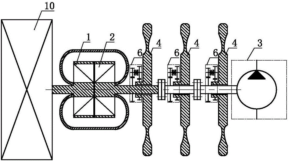
[0041] a power system such as figure 2 As shown, it includes an engine 10, an impeller A1 and an impeller B2, the engine 10 is set in transmission with the impeller A1, the impeller A1 and the impeller B2 are connected in series, and the impeller B2 is connected to the hydraulic pressure The pump 3 is set in transmission, and the impeller B 2 , the transmission member between the impeller B 2 and the hydraulic pump 3 , and the power shaft of the hydraulic pump 3 are all set in transmission with the inertia body 4 through the speed increasing mechanism 6 .
[0042] As a changeable embodiment, Embodiment 2 of the present invention can also selectively choose to make the impeller B 2, the transmission member between the impeller B 2 and the hydraulic pump 3 and the power shaft of the hydraulic pump 3 One or two of them are set through speed-up mechanism 6 and inertial body 4 transmission, and can further selectively select to make the remaining one or two parts not set inertia b...
Embodiment 3
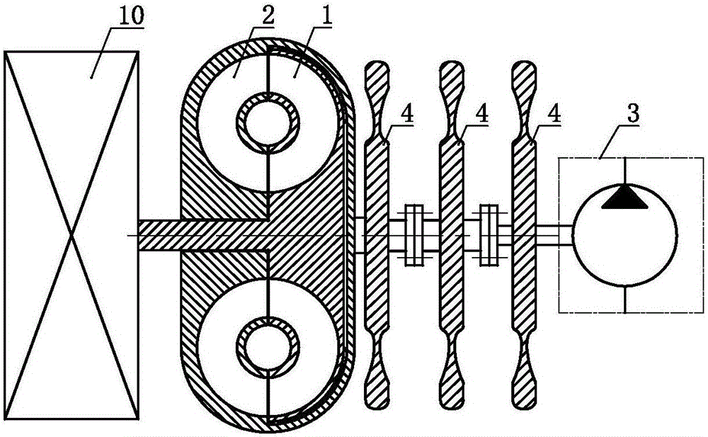
[0046] a power system such as Figure 3.1 and 3.2 As shown, it includes engine 10, impeller A 1, impeller B 2 and impeller AB 5, the engine 10 is set in transmission with the impeller A 1, and the impeller A 1, the impeller B 2 and the impeller AB 5 are connected in series The impeller B 2 is set in communication with the hydraulic pump 3 , and the inertia body 4 is set on the transmission member between the impeller B 2 and the hydraulic pump 3 and on the power shaft of the hydraulic pump 3 .
[0047] As a changeable embodiment, Embodiment 3 of the present invention can also selectively choose to make the impeller B 2, the transmission member between the impeller B 2 and the hydraulic pump 3, and the power shaft of the hydraulic pump 3 An inertia body 4 is set on one of them, or at least two of the impeller B 2, the transmission member between the impeller B 2 and the hydraulic pump 3, and the power shaft of the hydraulic pump 3 are set with inertia Body 4.
PUM
 Abstract
Description
Claims
Application Information
 - R&D
- Intellectual Property
- Life Sciences
- Materials
- Tech Scout
- Unparalleled Data Quality
- Higher Quality Content
- 60% Fewer Hallucinations
Browse by: Latest US Patents, China's latest patents, Technical Efficacy Thesaurus, Application Domain, Technology Topic, Popular Technical Reports.
© 2025 PatSnap. All rights reserved.Legal|Privacy policy|Modern Slavery Act Transparency Statement|Sitemap|About US| Contact US: help@patsnap.com


