
gas exchange entropy cycle engine

An engine and gas technology, applied in the field of gas exchange entropy cycle engines, can solve the problems of high material requirements, poor load response, and limited speed, and achieve broad application prospects, less pollution emissions, and good load response effects

Active Publication Date: 2015-10-28
吴江科技创业园管理服务有限公司
View PDF4 Cites 0 Cited by
  • Summary
  • Abstract
  • Description
  • Claims
  • Application Information

AI Technical Summary

Problems solved by technology

As we all know, it is difficult to obtain a working fluid with a higher temperature in the external combustion heating process, thus causing a large amount of chemical loss
Not only that, due to the limited rate of external combustion heating, high requirements on materials, and poor load response, this severely restricts the single-unit power and overall power density of the heat generator, and ultimately severely limits the use of the heat generator
Moreover, in the working process of the heat engine, not only the working mechanism needs to be heated, but also the compression mechanism needs to be cooled to realize the temperature difference, so that the heat engine can perform external work, but this will cause the engine to waste a lot of energy that can be used

Method used


Image

  • gas exchange entropy cycle engine
  • gas exchange entropy cycle engine
  • gas exchange entropy cycle engine

Examples


Embodiment 1

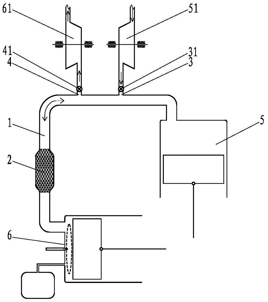
[0037] Such as figure 1 The air exchange entropy cycle engine shown includes a gas compression mechanism, a gas work mechanism and a communication channel 1, the gas compression mechanism is set as a piston type gas compression mechanism 5, and the gas work mechanism is set as a piston type gas work mechanism 6, The piston-type gas compression mechanism 5 communicates with the piston-type gas working mechanism 6 through the communication channel 1, and a regenerator 2 is arranged on the communication channel 1, and the regenerator 2 and the gas compression An oxidant inlet 3 and a working medium outlet 4 are provided on the communication channel 1 between the mechanisms, and the oxidant inlet 3 communicates with the auxiliary gas compression mechanism, and the auxiliary gas compression mechanism is set as an impeller-type auxiliary gas compression mechanism 51. An oxidant control valve 31 is provided on the communication channel between the oxidant inlet 3 and the impeller-typ...

Embodiment 2

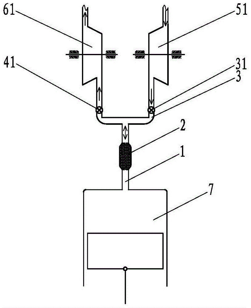
[0044] Such as figure 2 The air exchange entropy cycle engine shown includes a cylinder-piston mechanism 7, the cylinder of the cylinder-piston mechanism 7 communicates with the auxiliary gas work mechanism, and the auxiliary gas work mechanism is set as an impeller-type auxiliary gas work mechanism 61. A working fluid export control valve 41 is provided on the communication passage between the cylinder of the piston mechanism 7 and the auxiliary gas working mechanism, and on the communication passage between the working fluid export control valve 41 and the cylinder of the cylinder-piston mechanism 7 An oxidant inlet 3 is set, and the oxidant inlet 3 communicates with the auxiliary gas compression mechanism, and the auxiliary gas compression mechanism is set as an impeller-type auxiliary gas compression mechanism 51, and the An oxidant control valve 31 is provided on the communication channel, and a regenerator 2 is provided on the communication channel between the cylinder ...

Embodiment 3

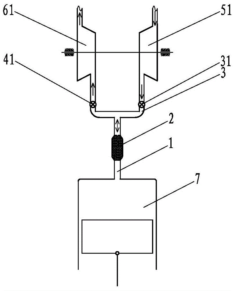
[0046] Such as image 3 The difference between the air exchange entropy cycle engine shown in Embodiment 2 is that the impeller-type auxiliary gas working mechanism 61 outputs power to the impeller-type auxiliary gas compression mechanism 51 .

[0047] During specific implementation, in all implementations of the present invention, this embodiment can be referred to to enable the auxiliary gas working mechanism to output power to the auxiliary gas compression mechanism.


PUM


Abstract

The invention disclose a gas exchange entropy circulation engine which comprises a gas compression mechanism, a gas acting mechanism and a communicating passage. The gas compression mechanism is communicated with the gas acting mechanism through the communicating passage. A heat regenerator is disposed on the communicating passage. An oxidant inlet and a working medium outlet are formed in the communicating passage between the heat regenerator and the gas compression mechanism or in the gas compression mechanism. The oxidant inlet is communicated with an auxiliary gas compression mechanism. An oxidant control valve is disposed on the communicating passage between the oxidant inlet and the auxiliary gas compression mechanism. The working medium outlet is communicated with an auxiliary gas acting mechanism. A working medium discharge control valve is disposed on the communicating passage between the working medium outlet and the auxiliary gas acting mechanism. The gas exchange entropy circulation engine has the advantages that internal combustion heating is used to increase efficiency and power density, and accordingly energy can be saved effectively, and size, weight and manufacturing cost of the engine can be reduced greatly.

Description

technical field [0001] The invention relates to the field of thermal energy and power, in particular to an air exchange entropy cycle engine. Background technique [0002] In recent years, the problems of high energy consumption and high pollution emission of traditional engines have become increasingly prominent. Therefore, heat engines have received extensive attention. However, heat engines heat the working fluid by means of external combustion heating. As we all know, it is difficult to obtain a higher temperature working fluid in the external combustion heating process, so a large amount of chemical loss. Not only that, due to the limited external combustion heating rate, high material requirements, and poor load response, the single-unit power and overall power density of the heat generator are severely restricted, and the use of the heat generator is severely limited in the end. Moreover, in the working process of the heat engine, not only the working mechanism nee...

Claims


Application Information

Patent Timeline
Patent Type & Authority Patents(China)
IPC IPC(8): F02G1/043F02G1/053
Inventor 靳北彪
Owner 吴江科技创业园管理服务有限公司
Learn More