
Overlapped heat radiation structure

A heat-dissipating structure and layered technology, applied in the field of lighting, can solve the problems of increasing heat dissipation demand of lamps, low overall structural stability, and affecting the heat dissipation performance of lamps and lanterns.

Active Publication Date: 2017-06-27
东莞市闻誉实业有限公司
View PDF7 Cites 2 Cited by
  • Summary
  • Abstract
  • Description
  • Claims
  • Application Information

AI Technical Summary

Problems solved by technology

[0003] Generally, the heat dissipation load of the existing lamps is fixed, that is, the heat dissipation load borne by the components that undertake the heat dissipation function in the lamps is fixed. However, when the lamp needs to install a lamp group or increase the power of the lamp group, it will inevitably cause The heat dissipation demand of the lamp is greatly increased. If the heat dissipation load borne by the components responsible for the heat dissipation function is fixed and cannot be changed, the heat dissipation performance of the lamp will be affected.
[0004] In particular, the overall structural stability of the parts that undertake the heat dissipation function of the existing lamps is relatively low

Method used


Image

  • Overlapped heat radiation structure
  • Overlapped heat radiation structure
  • Overlapped heat radiation structure

Examples


Embodiment Construction

[0025] In order to facilitate the understanding of the present invention, the present invention will be described more fully below with reference to the associated drawings. Preferred embodiments of the invention are shown in the accompanying drawings. However, the present invention can be embodied in many different forms and is not limited to the embodiments described herein. On the contrary, the purpose of providing these embodiments is to make the disclosure of the present invention more thorough and comprehensive.

[0026] It should be noted that when an element is referred to as being “fixed” to another element, it can be directly on the other element or there can also be an intervening element. When an element is referred to as being "connected to" another element, it can be directly connected to the other element or intervening elements may also be present. The terms "vertical," "horizontal," "left," "right," and similar expressions are used herein for purposes of ill...


PUM


Abstract

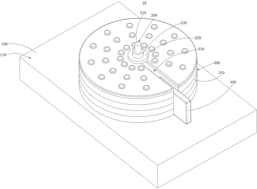
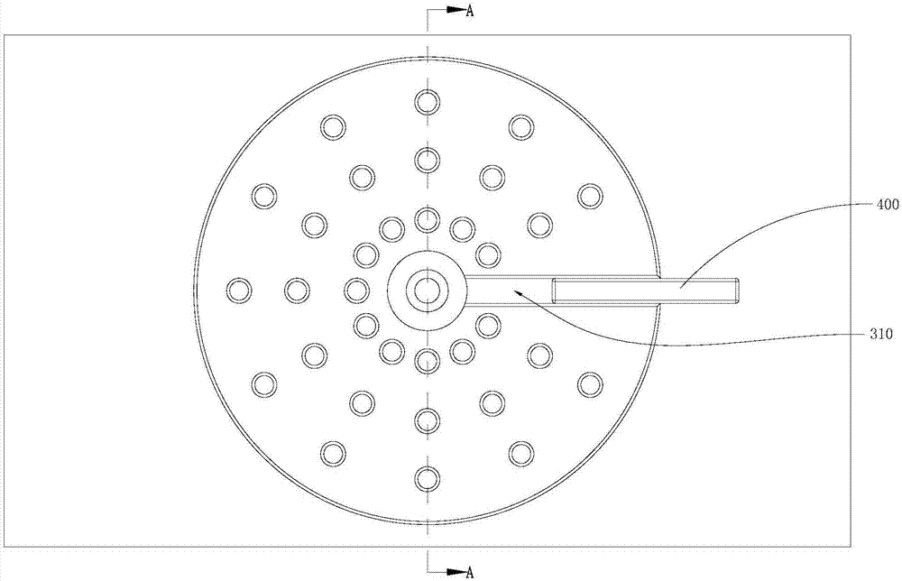
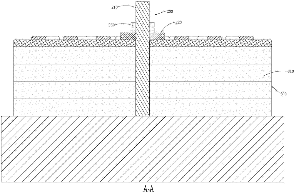
An overlapped heat radiation structure comprises a bearing abutment, a supporting assembly, an overlapped assembly and a guide plate. The bearing abutment is provided with an installing surface. The supporting assembly comprises a supporting rod, a buffering ring and a locking ring, the supporting rod is arranged on the installing surface and sleeved with the buffering ring and the locking ring, the locking ring and the supporting rod are in threaded connection, and the locking ring abuts against the side surface, far away from the bearing abutment, of the buffering ring. The overlapped assembly is arranged on the installing surface and clamped between the buffering ring and the bearing abutment. The overlapped assembly is provided with a receding groove, and the supporting rod is located in the receding groove. The overlapped assembly comprises a plurality of overlapped plates which are overlapped. The guide plate is arranged on the installing surface and located in the receding groove, and the guide plate abuts against the inner side wall of the receding groove. In this way, different heat radiation loads can be adjusted correspondingly by adjusting the number of the overlapped plates of the overlapped assembly. In addition, the overlapped assembly is clamped between the buffering ring and the bearing abutment, and the overall structure stability is higher.

Description

technical field [0001] The invention relates to the field of lighting technology, in particular to a stacked heat dissipation structure. Background technique [0002] Luminaires refer to appliances that can transmit light, distribute and change the light distribution of the light source, including all parts required to fix and protect the light source except the light source, as well as the necessary line accessories for connection to the power supply. Generally, in order to dissipate heat from the lamps and ensure the normal use of the lamps, the Radiator is used for the heat generated by the lamps when the lamps are working, so that the lamps can dissipate heat and cool to increase the service life of the lamps and ensure normal working performance. Therefore, the quality of the bearing base directly affects the life and normal working performance of the lamp. [0003] Generally, the heat dissipation load of the existing lamps is fixed, that is, the heat dissipation load...

Claims


Application Information

Patent Timeline
Patent Type & Authority Applications(China)
IPC IPC(8): F21V29/73
CPCF21V29/73
Inventor 叶伟炳
Owner 东莞市闻誉实业有限公司
Learn More