Measuring jig
A jig and voltage pin technology, applied in the direction of measuring electricity, measuring devices, measuring electrical variables, etc., can solve the problem of insufficient use of test fixtures, and achieve the effect of diversified measurement functions
- Summary
- Abstract
- Description
- Claims
- Application Information
AI Technical Summary
Problems solved by technology
Method used
Image
Examples
Embodiment Construction
[0029] The detailed features and advantages of the present invention are described in detail in the following embodiments. The content is sufficient to enable those skilled in the art to understand the technical content of the present invention and implement it accordingly. According to the content disclosed in this specification, claims and drawings, this Those skilled in the art can easily understand the related objects and advantages of the present invention. The following examples illustrate the viewpoints of the present invention in further detail, but do not limit the scope of the present invention by any viewpoint.
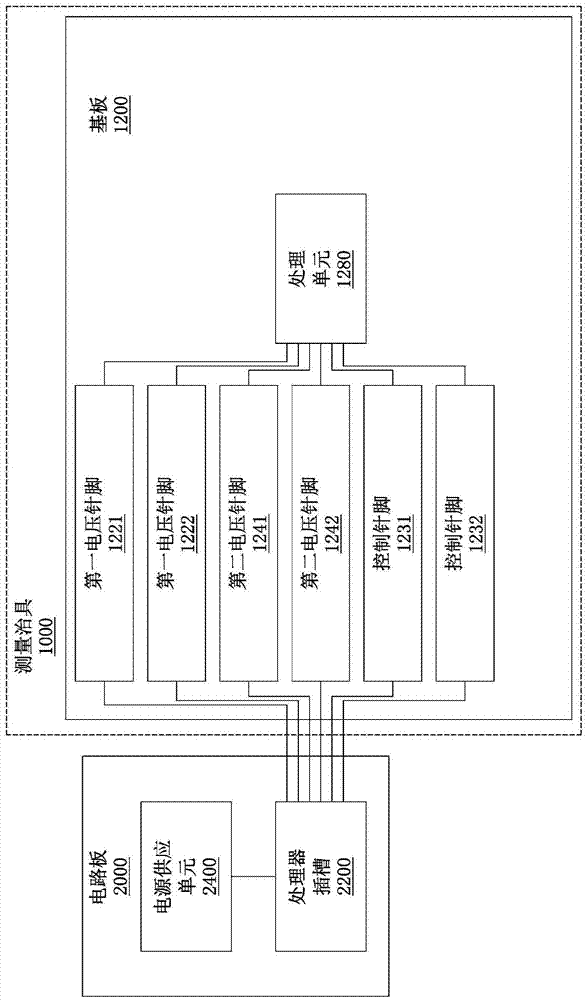
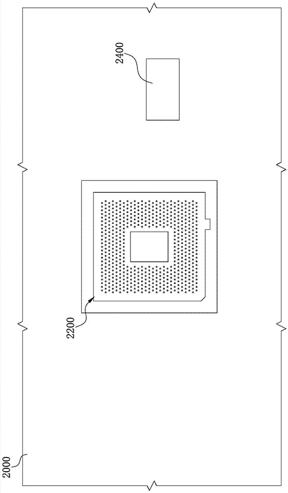
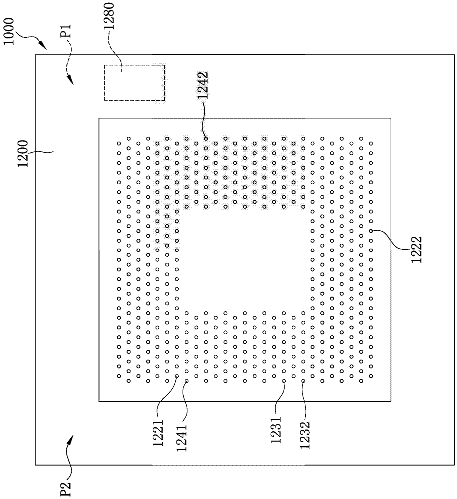
[0030] Please refer to figure 1 , figure 1 It is a functional block diagram of a measuring fixture according to an embodiment of the invention. Such as figure 1 As shown, the measuring jig 1000 is suitable for being inserted into the processor socket 2200 on the motherboard 2000. The measuring jig 1000 includes a substrate 1200, first voltage pins 1221, 1222,...
PUM
 Abstract
Description
Claims
Application Information
 - R&D
- Intellectual Property
- Life Sciences
- Materials
- Tech Scout
- Unparalleled Data Quality
- Higher Quality Content
- 60% Fewer Hallucinations
Browse by: Latest US Patents, China's latest patents, Technical Efficacy Thesaurus, Application Domain, Technology Topic, Popular Technical Reports.
© 2025 PatSnap. All rights reserved.Legal|Privacy policy|Modern Slavery Act Transparency Statement|Sitemap|About US| Contact US: help@patsnap.com


