Acrylic plate vibration measurement system and device based on ultrasonic waves
An acrylic plate, vibration measurement technology, applied in the direction of measurement device, vibration test, machine/structural component testing, etc., can solve the problems of one-sided measurement results, single measurement function, difficult acrylic plate vibration performance measurement and analysis, etc., to ensure accurate The effect of high stability, high measurement efficiency, simple fixing method and fixing structure
- Summary
- Abstract
- Description
- Claims
- Application Information
AI Technical Summary
Problems solved by technology
Method used
Image
Examples
Embodiment 1
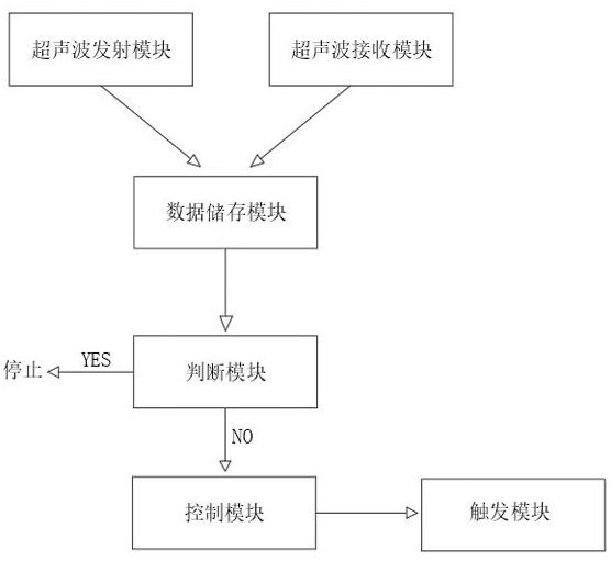
[0043] see figure 1 , the present invention provides a technical solution: an ultrasonic-based acrylic plate vibration measurement system, including:
[0044] A trigger module, the trigger module is provided with an acrylic plate, and the trigger module strikes the acrylic plate to cause vibration;
[0045] An ultrasonic transmitting module, the ultrasonic transmitting module is internally provided with an ultrasonic transmitting component and a timing component, the ultrasonic transmitting module transmits ultrasonic waves to act on the plate to be tested and reflects the ultrasonic waves back through the plate to be tested;
[0046] Ultrasonic receiving module, the ultrasonic receiving module is equipped with an ultrasonic receiving component and a timing component, the ultrasonic receiving module can receive the ultrasonic wave reflected from the plate to be tested and calculate the time difference through the timing component;
[0047] A data storage module, the data stor...
Embodiment 2
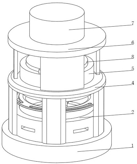
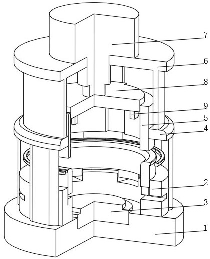
[0052] see Figure 1-4 On the basis of Embodiment 1, the present invention provides a technical solution: an ultrasonic-based acrylic plate vibration measurement device, specifically comprising:
[0053] A base 1, the top of the base 1 is fixedly connected with a fixing device 2, and the center of the top of the base 1 is fixedly connected with an ultrasonic transceiver device 3;
[0054] A support frame 4, the support frame 4 is arranged on the outside of the fixing device 2, and the center position of the top of the support frame 4 penetrates and is fixedly connected with a guide sleeve 5;
[0055] Upper bracket 6, the upper bracket 6 is arranged on the top of the support frame 4, the top of the upper bracket 6 is fixedly connected with the cylinder 7, the end of the push rod inside the cylinder 7 is fixedly connected with the knocking disc 8, and the bottom of the knocking disc 8 is fixedly connected with the knocking disc 8. hit head 9;
[0056] The ultrasonic-based acry...
Embodiment 3
[0063] see Figure 1-5 , on the basis of Embodiment 1 and Embodiment 2, the present invention provides a technical solution: the annular pressure ring 25 includes a pressure ring body 251, the outer side of the top of the pressure ring body 251 is fixedly connected with a rotating ring 252, and the bottom of the pressure ring body 251 is provided with Rolling chute 253, the bottom of the inner wall of rolling chute 253 is provided with ball groove 254, the inner wall of ball groove 254 is slidably connected with support ball 255, the part of the inner wall of rolling chute 253 located below the support ball 255 is slidably connected with washer 256, and the annular pressure ring 25 It is arranged inside the thread groove 23 and threadedly connected with the inner wall of the thread groove 23. The ball groove 254 is provided with multiple groups and evenly distributed inside the rolling chute 253. The side of the washer 256 is slidingly connected with the inner wall of the rolli...
PUM
 Abstract
Description
Claims
Application Information
 - R&D
- Intellectual Property
- Life Sciences
- Materials
- Tech Scout
- Unparalleled Data Quality
- Higher Quality Content
- 60% Fewer Hallucinations
Browse by: Latest US Patents, China's latest patents, Technical Efficacy Thesaurus, Application Domain, Technology Topic, Popular Technical Reports.
© 2025 PatSnap. All rights reserved.Legal|Privacy policy|Modern Slavery Act Transparency Statement|Sitemap|About US| Contact US: help@patsnap.com


