Factory fire alarm device
An alarm equipment and fire protection technology, applied in the direction of mechanical fire alarms, etc., can solve the problem of not targeting the easy ignition point of the factory, and achieve the effect of improving the alarm effect, increasing the friction force, and facilitating the opening of the cover.
- Summary
- Abstract
- Description
- Claims
- Application Information
AI Technical Summary
Problems solved by technology
Method used
Image

Examples
Embodiment 1
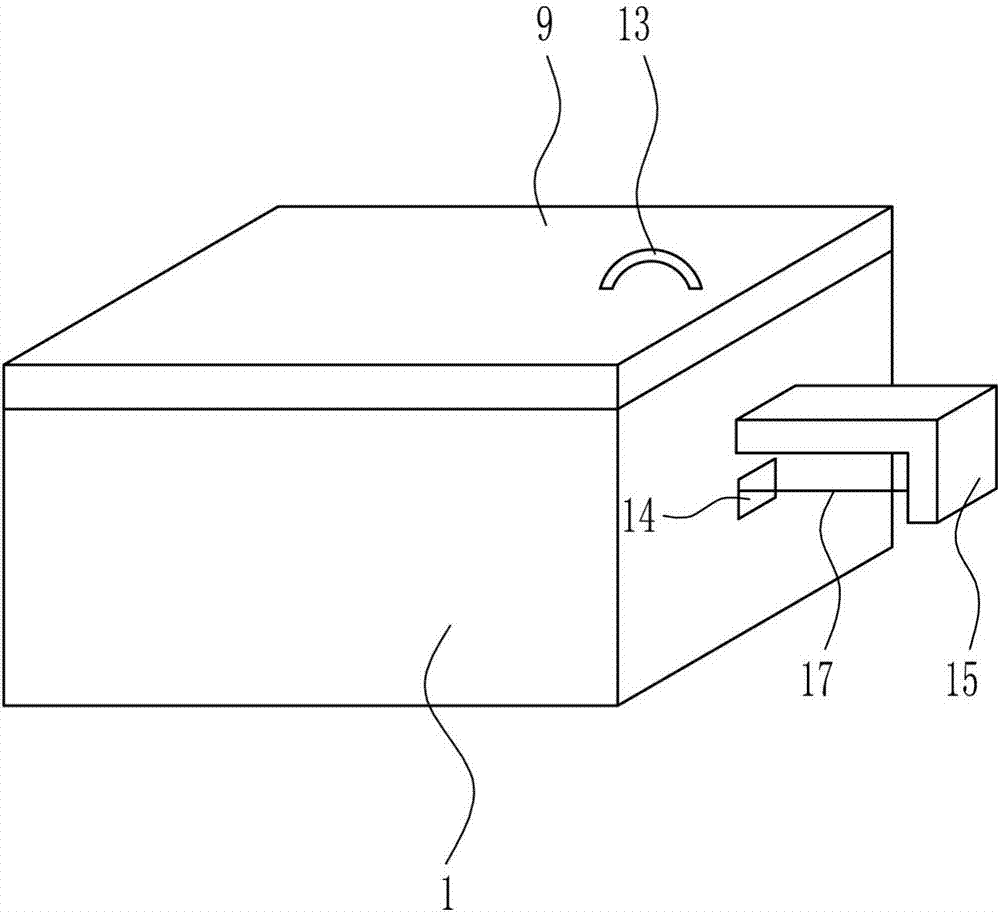
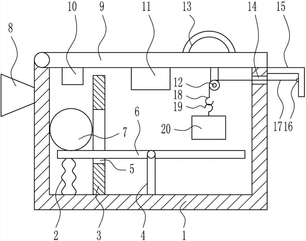
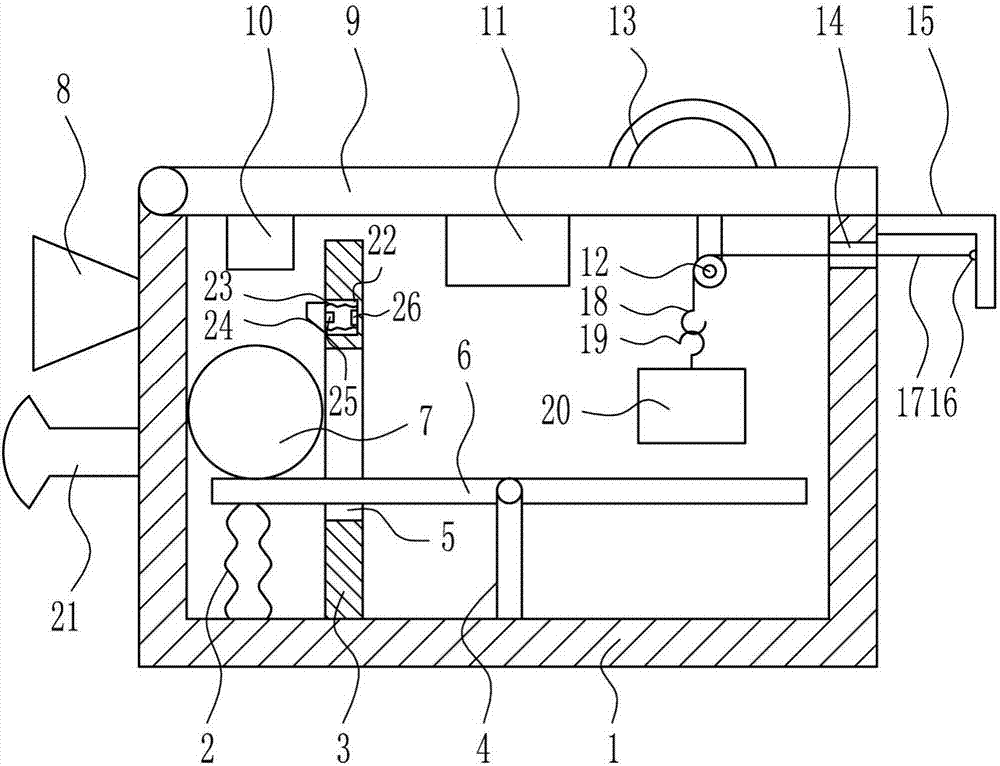
[0025] A factory fire alarm equipment, such as Figure 1-4 As shown, it includes a housing 1, a first spring 2, a baffle plate 3, a support rod 4, a swing plate 6, a steel ball 7, a buzzer 8, a cover plate 9, a first button 10, a battery 11, a fixed pulley 12, Handle 13, L-shaped plate 15, hanging ring 16, pull wire 17, first hook 18, second hook 19 and first pressing block 20, the inner bottom of housing 1 is provided with first spring 2 and baffle in turn from left to right 3 and the support rod 4, the top of the support rod 4 is hingedly connected with a swing plate 6, the middle part of the baffle plate 3 has a word hole 5, the left part of the swing plate 6 passes through the word hole 5, the left side of the swing plate 6 bottom and the first spring 2 The top is connected, the steel ball 7 is placed on the left side of the top of the swing plate 6, the buzzer 8 is installed on the upper left side of the housing 1, the top of the left wall of the housing 1 is rotatably co...
Embodiment 2
[0027] A factory fire alarm equipment, such as Figure 1-4 As shown, it includes a housing 1, a first spring 2, a baffle plate 3, a support rod 4, a swing plate 6, a steel ball 7, a buzzer 8, a cover plate 9, a first button 10, a battery 11, a fixed pulley 12, Handle 13, L-shaped plate 15, hanging ring 16, pull wire 17, first hook 18, second hook 19 and first pressing block 20, the inner bottom of housing 1 is provided with first spring 2 and baffle in turn from left to right 3 and the support rod 4, the top of the support rod 4 is hingedly connected with a swing plate 6, the middle part of the baffle plate 3 has a word hole 5, the left part of the swing plate 6 passes through the word hole 5, the left side of the swing plate 6 bottom and the first spring 2 The top is connected, the steel ball 7 is placed on the left side of the top of the swing plate 6, the buzzer 8 is installed on the upper left side of the housing 1, the top of the left wall of the housing 1 is rotatably co...
Embodiment 3
[0030] A factory fire alarm equipment, such as Figure 1-4As shown, it includes a housing 1, a first spring 2, a baffle plate 3, a support rod 4, a swing plate 6, a steel ball 7, a buzzer 8, a cover plate 9, a first button 10, a battery 11, a fixed pulley 12, Handle 13, L-shaped plate 15, hanging ring 16, pull wire 17, first hook 18, second hook 19 and first pressing block 20, the inner bottom of housing 1 is provided with first spring 2 and baffle in turn from left to right 3 and the support rod 4, the top of the support rod 4 is hingedly connected with a swing plate 6, the middle part of the baffle plate 3 has a word hole 5, the left part of the swing plate 6 passes through the word hole 5, the left side of the swing plate 6 bottom and the first spring 2 The top is connected, the steel ball 7 is placed on the left side of the top of the swing plate 6, the buzzer 8 is installed on the upper left side of the housing 1, the top of the left wall of the housing 1 is rotatably con...
PUM
 Abstract
Description
Claims
Application Information
 - R&D Engineer
- R&D Manager
- IP Professional
- Industry Leading Data Capabilities
- Powerful AI technology
- Patent DNA Extraction
Browse by: Latest US Patents, China's latest patents, Technical Efficacy Thesaurus, Application Domain, Technology Topic.
© 2024 PatSnap. All rights reserved.Legal|Privacy policy|Modern Slavery Act Transparency Statement|Sitemap