Spotlight positioning automatic following system

An automatic follow-up and specific technology, applied in the direction of lamp circuit layout, lighting device, light source, etc., can solve the problems of inconvenient operation, dangerous operation, poor effect of intelligent switching, etc., and achieve the effect of avoiding dangerous operation

Pending Publication Date: 2017-06-27
惠州雷士光电科技有限公司
View PDF7 Cites 4 Cited by
  • Summary
  • Abstract
  • Description
  • Claims
  • Application Information

AI Technical Summary

Problems solved by technology

[0003] The switch of this kind of light or the mode switch of the overall lighting effect often requires special personnel to operate, the operation is not intuitive enough, it is easy to cause misoperation, and the effect of intelligent switching is poor; sometimes these angle adjustments also require high-altitude operations, which will cause the operation The inconvenience and the danger of operation

Method used


Image

  • Spotlight positioning automatic following system
  • Spotlight positioning automatic following system
  • Spotlight positioning automatic following system

Examples


Embodiment 1

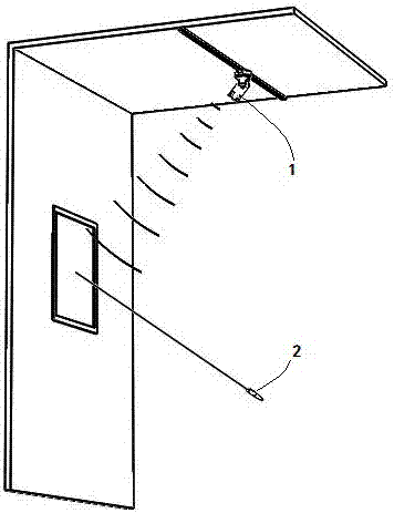
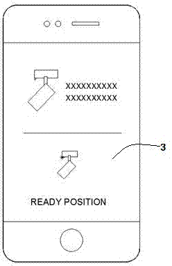
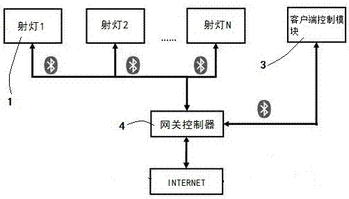
[0032] figure 1 A schematic structural diagram of the spotlight positioning automatic follow system of this embodiment is given, figure 2 A schematic diagram of the interface of the client control module of this embodiment is given, image 3 It is a schematic diagram of the communication connection of the spotlight positioning automatic follow system in this embodiment, combined with Figure 1~Figure 3 , an automatic follow-up system for spotlight positioning, comprising a spotlight 1, an image generating device 2, a client control module 3 and a gateway controller 4, wherein the spotlight 1 is provided with a spotlight control module 11, the spotlight control module 11 and The gateway controller 4 is connected in wireless communication; the image generating device 2 emits irradiation spots or specific irradiation patterns.

[0033] The image generation device 2 may be a positioning laser pointer, or other image generation devices capable of irradiating and forming specific...

Embodiment 2

[0046] Figure 6 An explanatory block diagram of the spotlight positioning automatic follow system of this embodiment is given. When the operator turns on the auto-follow function on the client control module to make the spotlight ready for automatic light follow, the indicator light of the spotlight will flash quickly, indicating that the spotlight enters the light auto-follow mode. combine Figure 6 The explanatory block diagram of , the operator uses the image generation device to point to the target, and the specific irradiation pattern or irradiation point irradiated by the image generation device 2 stays on the display item for positioning, and the general residence time is more than 2S.

[0047] At this time, the tracking and identification module of the spotlight is mainly to obtain the location where the target is pointed by the CCD, obtain the positioning target, and calculate the specific irradiation pattern or the orientation of the irradiation point of the image ...


PUM


Abstract

The present invention provides a spotlight positioning automatic following system. The system comprises a spotlight, an image generation device, a client control module and a gateway controller. The spotlight is provided with a spotlight control module which is in wireless communication connection with the gateway controller, the spotlight control module controls the beam of the spotlight to follow a specific irradiation pattern or irradiation point irradiated by the image generation device to move, and the spotlight can regulates the irradiation angle and position according to a operator's demand. The operator also can regulate the color temperature and brightness of the light on the client control module so as to reach a perfect object display effect while attracting eyeballs.

Description

technical field [0001] The invention relates to the technical field of LED lighting, in particular to an automatic tracking system for spotlight positioning. Background technique [0002] As a lighting fixture for object accent lighting, LED track spotlights are usually used for commodity display lighting, interior decoration, exhibition hall lighting, etc. The lighting of spotlights includes a variety of areas and types. When the placement of objects changes, it is often necessary to adjust the lighting angle of spotlights to determine the direction of their target lighting. The lighting control methods of spotlights are all centralized control through a large number of centralized manual switches or rotary buttons, or computer central control systems. [0003] The switch of this kind of light or the mode switch of the overall lighting effect often requires special personnel to operate, the operation is not intuitive enough, it is easy to cause misoperation, and the effect...

Claims


Application Information

Patent Timeline
Patent Type & Authority Applications(China)
IPC IPC(8): H05B37/02
CPCH05B47/19
Inventor 洪晓松林春喜
Owner 惠州雷士光电科技有限公司
Why Eureka
Try Eureka