
The pressure stabilization control system of the reaction tank

A technology of voltage stabilization control and reaction tank, which is applied in the control/regulation process, pressure vessel used in chemical process, chemical/physical/physical-chemical process, etc. The cost increase and other problems, to achieve the effect of reducing uncontrollable factors of product quality, eliminating potential safety hazards, and reducing production costs

Active Publication Date: 2019-03-22
SINO MAGNETICS TECH
View PDF3 Cites 0 Cited by
  • Summary
  • Abstract
  • Description
  • Claims
  • Application Information

AI Technical Summary

Problems solved by technology

[0003] 1. There are a large number of human factors in the operation process, which makes the control range of the pressure value of the reaction tank inaccurate, and the process parameters cannot be strictly implemented, resulting in an increase in uncontrollable factors of product quality
[0004] 2. Employees may forget to close the inflation valve at a critical moment, causing the internal pressure of the reaction tank to continue to rise, causing explosion accidents, posing safety hazards, resulting in increased maintenance costs and increased production costs

Method used


Image

  • The pressure stabilization control system of the reaction tank
  • The pressure stabilization control system of the reaction tank

Examples


Embodiment Construction

[0015] The specific embodiments of the present invention will be described in detail below in conjunction with the accompanying drawings, but it should be understood that the protection scope of the present invention is not limited by the specific embodiments.

[0016] Unless expressly stated otherwise, throughout the specification and claims, the term "comprise" or variations thereof such as "includes" or "includes" and the like will be understood to include the stated elements or constituents, and not Other elements or other components are not excluded.

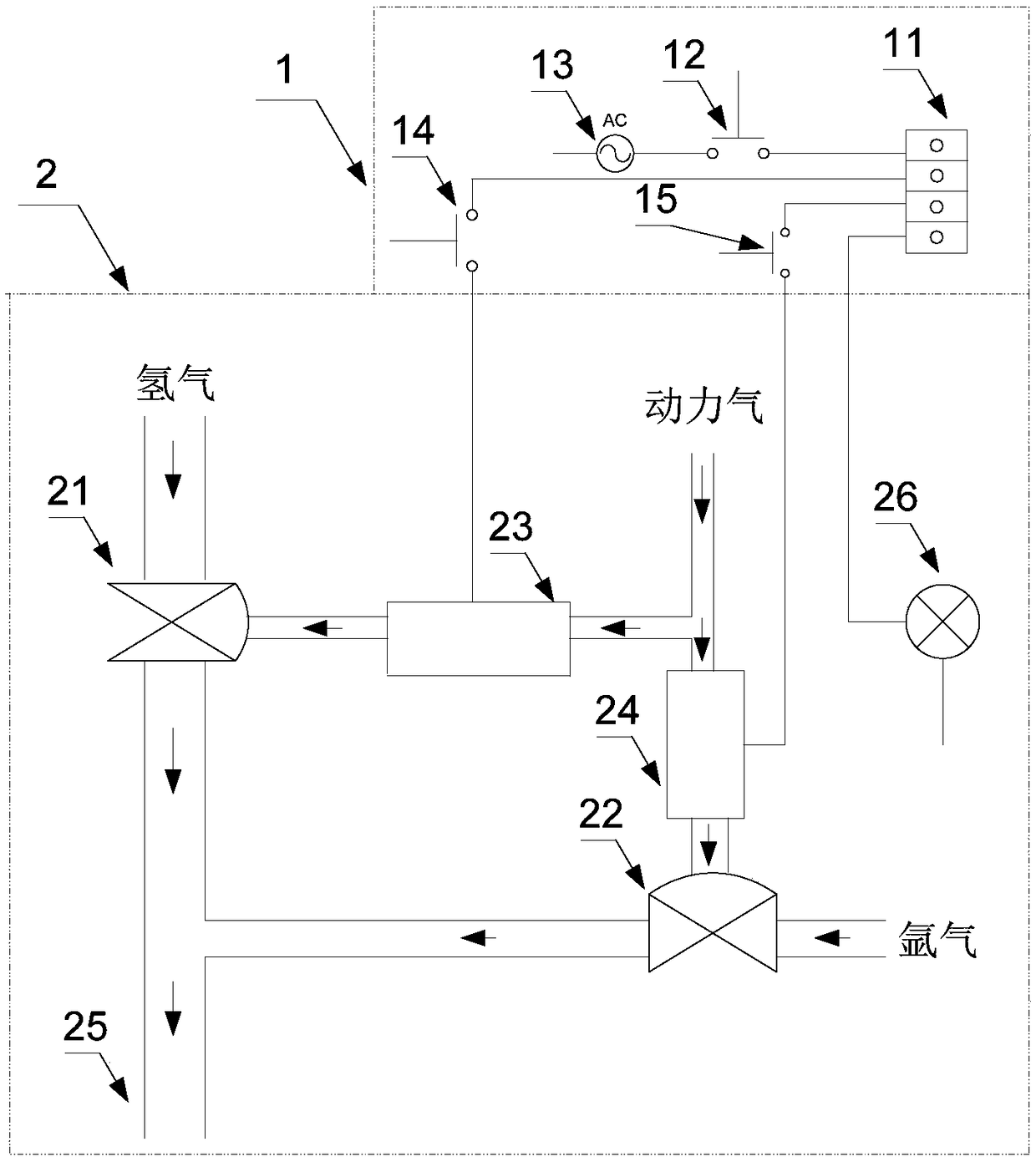
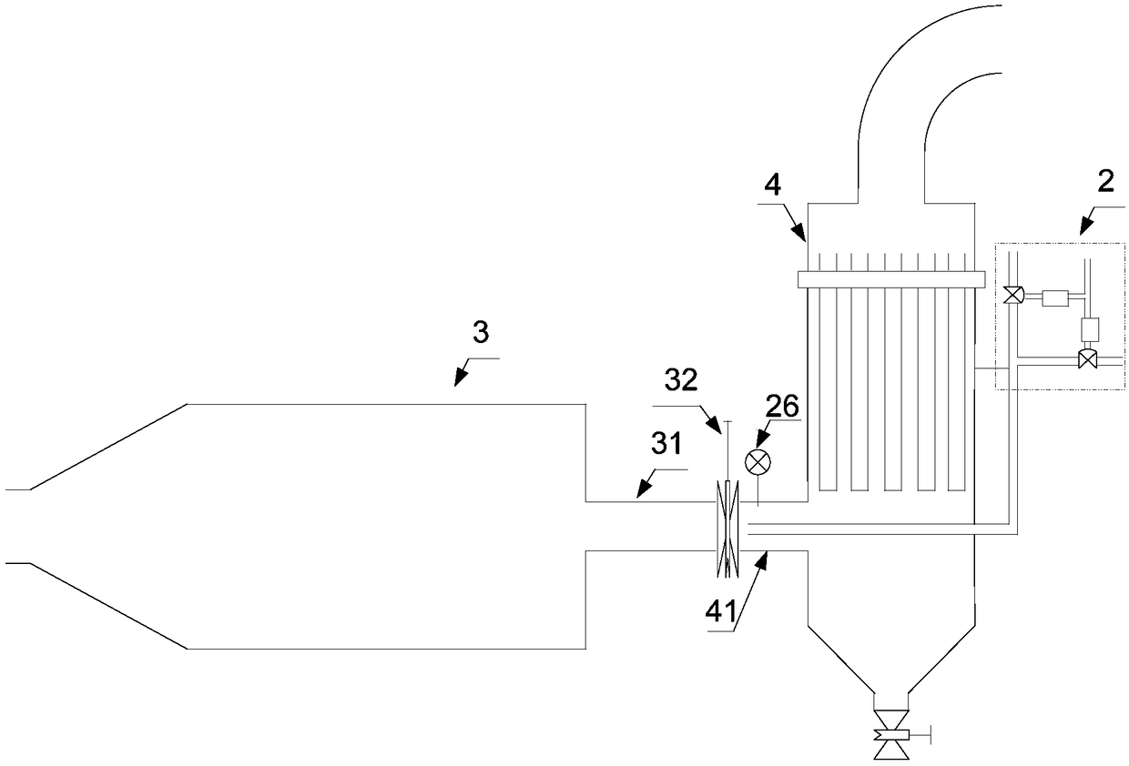
[0017] Such as Figure 1 to Figure 2 As shown, according to a kind of pressure stabilization control system of the reaction tank according to the specific embodiment of the present invention, the reaction tank 3 is connected with the filter 4, and the filter 4 is used to filter the outflow from the reaction tank 3 when the reaction tank 3 is exhausted. Powder, the voltage stabilization control system includes a control gas...


PUM


Abstract

The invention discloses a reaction tank steady pressure control system including a control gas channel and a control subsystem; the control gas channel includes power gas, a gas inlet pipe, a hydrogen gas channel and an argon gas channel; the gas inlet pipe passes through a filter and extends to a junction of a reaction tank and the filter; the hydrogen gas channel includes a hydrogen gas source and a first vacuum diaphragm valve, the hydrogen gas source communicates with the gas inlet pipe through the first vacuum diaphragm valve, and the first vacuum diaphragm valve communicates with the power gas through a first solenoid valve; the argon gas channel includes an argon gas source and a second vacuum diaphragm valve, the argon gas source communicates with the gas inlet pipe through the second vacuum diaphragm valve, and the second vacuum diaphragm valve communicates with the power gas through a second solenoid valve; the control subsystem includes a pressure detector and a controller; the pressure detector is arranged at the junction of the reaction tank and the filter; the controller is used for comparing a signal acquired by the pressure detector with an upper limit value or a lower limit value, so as to control opening and closing of the first solenoid valve and the second solenoid valve. The control system can realize control of the pressure value range in the reaction tank accurately.

Description

technical field [0001] The invention relates to the field of NdFeB production, in particular to a voltage stabilization control system for a reaction tank. Background technique [0002] The hydrogen crushing process is a key process in the production of NdFeB magnetic materials, and the hydrogen crushing reaction tank is the main component of the hydrogen crushing equipment. The entire hydrogen breaking process is carried out inside the reaction tank. During the hydrogen breaking process, it is necessary to fill the reaction tank with hydrogen or argon at a certain pressure. Whether it is filled with hydrogen or argon, the pressure of the reaction tank must be guaranteed. The value is within a certain range, which requires a certain method to strictly control the pressure value of the reaction tank within a certain range in the process control of hydrogen production. In this process, most manufacturers set up special employees to manually control the switch of the argon val...

Claims


Application Information

Patent Timeline
Patent Type & Authority Patents(China)
IPC IPC(8): B01J19/00B01J3/04B22F9/02
CPCB01J3/04B01J19/0006B01J2219/00162B22F9/023
Inventor 马毅恒王明选
Owner SINO MAGNETICS TECH
Learn More