Back-flow preventer used for controlling liquid of micro-fluidic chip and micro-fluidic chip thereof

A technology of anti-reflux device and microfluidic chip, which can be used in fluid controllers, laboratory containers, laboratory utensils, etc., and can solve the problem of insufficient flux.

Active Publication Date: 2017-06-30
NANJING LANSION BIOTECH CO LTD
View PDF8 Cites 15 Cited by
  • Summary
  • Abstract
  • Description
  • Claims
  • Application Information

AI Technical Summary

Problems solved by technology

This will have a problem that

Method used


Image

  • Back-flow preventer used for controlling liquid of micro-fluidic chip and micro-fluidic chip thereof
  • Back-flow preventer used for controlling liquid of micro-fluidic chip and micro-fluidic chip thereof
  • Back-flow preventer used for controlling liquid of micro-fluidic chip and micro-fluidic chip thereof

Examples


Embodiment 1

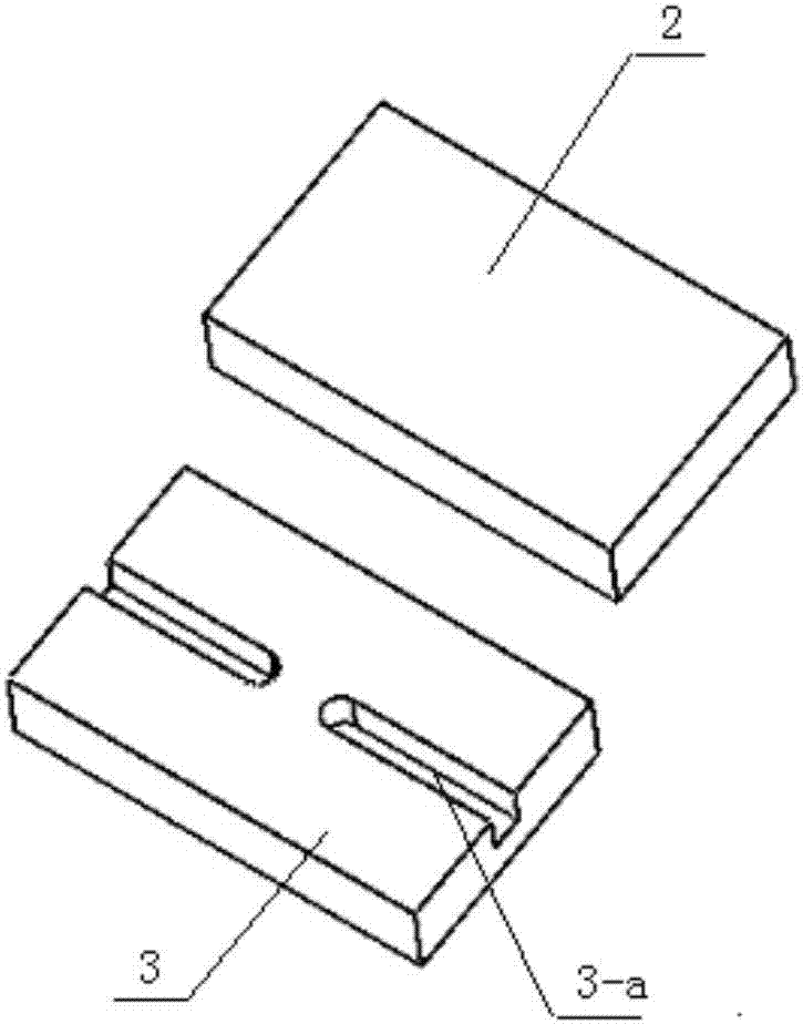
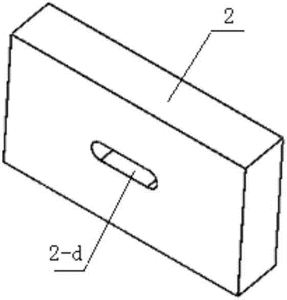
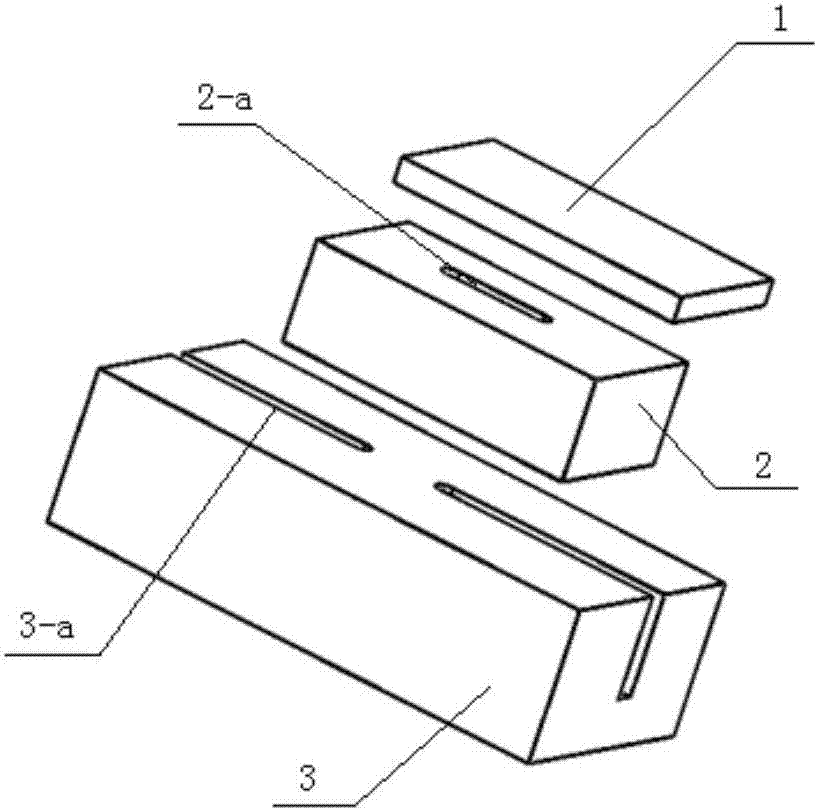
[0042] like Figure 1-2As shown, the anti-backflow structure described in this embodiment includes an anti-backflow channel 2-d (set in the middle chip 2), and the extension direction of the anti-backflow channel 2-d is in line with the microflow at the installation position of the anti-backflow structure. The extension direction of the flow control channel 3-a (set on the lower chip 3) is vertical; the microfluidic flow channel 3-a at the installation position of the backflow prevention structure is divided into two sections by the microfluidic flow channel spacer 3-b, They are the microfluidic liquid inlet channel and the microfluidic liquid outlet channel; the upper end of the anti-backflow channel 2-d is closed, and the lower end is bridged above the microfluidic channel spacer 3-b, and connected to the microfluidic channel spacer 3-b respectively. The fluidic inlet channel and the microfluidic outlet channel are connected; when the air circuit is connected, the fluid in t...

Embodiment 2

[0045] like Figure 3-4 As shown, the difference between the anti-reflux structure described in this embodiment and Embodiment 1 is:

[0046] 1. The anti-backflow channel 2-d has an anti-backflow bump 2-c, and two anti-backflow communication channels 2-c are formed between the anti-backflow bump 2-c and the anti-backflow channel 2-d b; the two anti-backflow communication channels 2-b are respectively connected with the microfluidic liquid inlet channel and the microfluidic liquid outlet channel; The lower end of -d is flush, and the upper end of the anti-backflow protrusion 2-c is set lower than the upper end of the anti-backflow channel 2-d.

[0047] 2. The upper end of the anti-backflow channel 2-d is closed by the cover provided by the upper chip 1.

[0048] It can be seen from this that the creative anti-backflow structure protruding above the surface of the microfluidic liquid in this embodiment can significantly prevent the backflow of the liquid. At the same time, th...

Embodiment 3

[0050] like Figure 5-8 As shown, the difference between the anti-reflux structure described in this embodiment and Embodiment 2 is:

[0051] The microfluidic channel block 3-b is set as a wedge-shaped block, and the anti-backflow channel 2-d is a wedge-shaped groove similar in shape to the microfluidic channel block 3-b.

[0052] It can be seen from this that since this embodiment has a raised flow channel, it can significantly prevent backflow.


PUM


Abstract

The invention relates to a back-flow preventer used for controlling liquid of a micro-fluidic chip and the micro-fluidic chip thereof. The back-flow preventer comprises a micro-fluidic channel and a back-flow preventing structure, the back-flow preventing structure is positioned over the micro-fluidic channel and has a back-flow preventing channel; the back-flow preventing channel can lift the liquid level height of the micro-fluidic channel at the installation position of a back-flow preventing structure; when the micro-fluidic channel is connected with the air passage, under driving of air pressure provided by air passage, liquid level height pressure of the micro-fluidic channel which is lifted by the back-flow preventing channel is overcome, and the liquid in the micro-fluidic channel at two sides of the back-flow preventer is urged to a circulation state. The back-flow preventer has good back-flow preventing function.

Description

technical field [0001] The invention relates to a liquid control anti-backflow device for a microfluidic chip and a microfluidic chip comprising the backflow device. Background technique [0002] Immunolateral flow-through diagnostic technology is a stable and practical technology suitable for use in various point-of-care tests (POCT) or on-site. [0003] In the immune system response system, the CV is large due to system reasons, and accurate quantification cannot be achieved. The immunodiagnostic method based on microfluidic technology can effectively avoid the above problems. [0004] There are two types of microfluidics: passive and active. Passive microfluidics still requires capillary force to achieve liquid-forward lateral flow. However, due to the different viscosities of different samples, especially whole blood samples, the liquid flow rate cannot be uniform. [0005] Active microfluidics can effectively avoid the above problems, and can give forward thrust to ...

Claims


Application Information

Patent Timeline
IPC IPC(8): B01L3/00
CPCB01L3/50273B01L3/502746B01L2200/0636B01L2300/089B01L2400/0487
Inventor 王龙孙威严万其露
Owner NANJING LANSION BIOTECH CO LTD
Why Eureka
Try Eureka