Vehicle-mounted hoisting fixed platform of rotor-wing type unmanned aerial vehicle

A fixed platform and unmanned aerial vehicle technology, applied in the field of vehicle-mounted platforms, can solve the problems of unsatisfactory and difficult control of unmanned aerial vehicles, and achieve the effect of simple and fast installation and easy accumulation of water.

Active Publication Date: 2017-06-30
BEIJING INSTITUTE OF TECHNOLOGYGY
5 Cites 15 Cited by

AI-Extracted Technical Summary

Problems solved by technology

Due to the characteristics of multi-variable, nonlinear, strong coupling and other characteristics of rotor UAV, it is difficult to control. In the process of dynam...

Method used

A large amount of high-speed airflows that produce in the process of unmanned aerial vehicle landing, as shown in Figure 11, the present embodiment is processed with air diversion groove 23 around rain cover 2, can make this airflow lead away in time, avoids air backflow Affects the landing of drone 7.
As shown in Figure 13, UAV fixture is provided with the circumferential groove that engages with clip bar; Fixed beam 11 as shown in Figure 5, fixed beam 11 is the skeleton of whole vehicle-mounted take-off and landing fixed platform, bears the whole The weight of the vehicle-mounted take-off and landing fixed platform. As shown in Figure 3 and Figure 4, the fixed beam 11 is fixed on the top of the car through the fixed hole 13 on the luggage rack 1, and the clamping rod moving device 10 is installed on the fixed beam 11, and the clamping rod moving device 10 moves under the drive of the driving mechanism , to achieve engagement and separation with the circumferential groove of the UAV fixing part, thereby realizing the fixation and separation of the UAV 7 and the vehicle-mounted take-off and landing fixed platform.
As shown in Figure 7 and Figure 9, the two ends of synchronous belt 18 are respectively supported by the synchronous pulley 19 of stepping motor 30 ends and the synchronous pulley 19 of the other end, and guide rail 17 is fixed on the U-shaped aluminum, and guide rail 17 2 each at the front and rear, and are symmetrically distributed along the front and rear cent...

Abstract

The invention discloses a vehicle-mounted hoisting fixed platform of a rotor-wing type unmanned aerial vehicle. The vehicle-mounted hoisting fixed platform of the unmanned aerial vehicle is composed of an unmanned aerial vehicle fixing part, a clamping rod movement device, a fixing beam and a driving mechanism; peripheral devices comprise the unmanned aerial vehicle and an automobile; the unmanned aerial vehicle fixing part is provided with a peripheral groove clamped with a clamping rod; the fixing beam is fixed at the top of the automobile; the clamping rod movement device is mounted on the fixing beam; the clamping rod movement device is driven by the driving mechanism to move to realize clamping and separation of the peripheral groove of the unmanned aerial vehicle fixing part, so that fixation and separation of the unmanned aerial vehicle and the vehicle-mounted hoisting fixed platform are realized. The vehicle-mounted hoisting fixed platform of the rotor-wing type unmanned aerial vehicle is simple and rapid to mount and can be used for rapidly eliminating deposited water of the vehicle-mounted platform and eliminating influences, caused by reflowing air, on the descending of the unmanned aerial vehicle.

Application Domain

Portable landing padsVehicle carriers

Technology Topic

Marine engineeringUncrewed vehicle

Image

  • Vehicle-mounted hoisting fixed platform of rotor-wing type unmanned aerial vehicle
  • Vehicle-mounted hoisting fixed platform of rotor-wing type unmanned aerial vehicle
  • Vehicle-mounted hoisting fixed platform of rotor-wing type unmanned aerial vehicle

Examples

  • Experimental program(1)

Example Embodiment

[0037] The present invention will be described in detail below with reference to the accompanying drawings and examples.
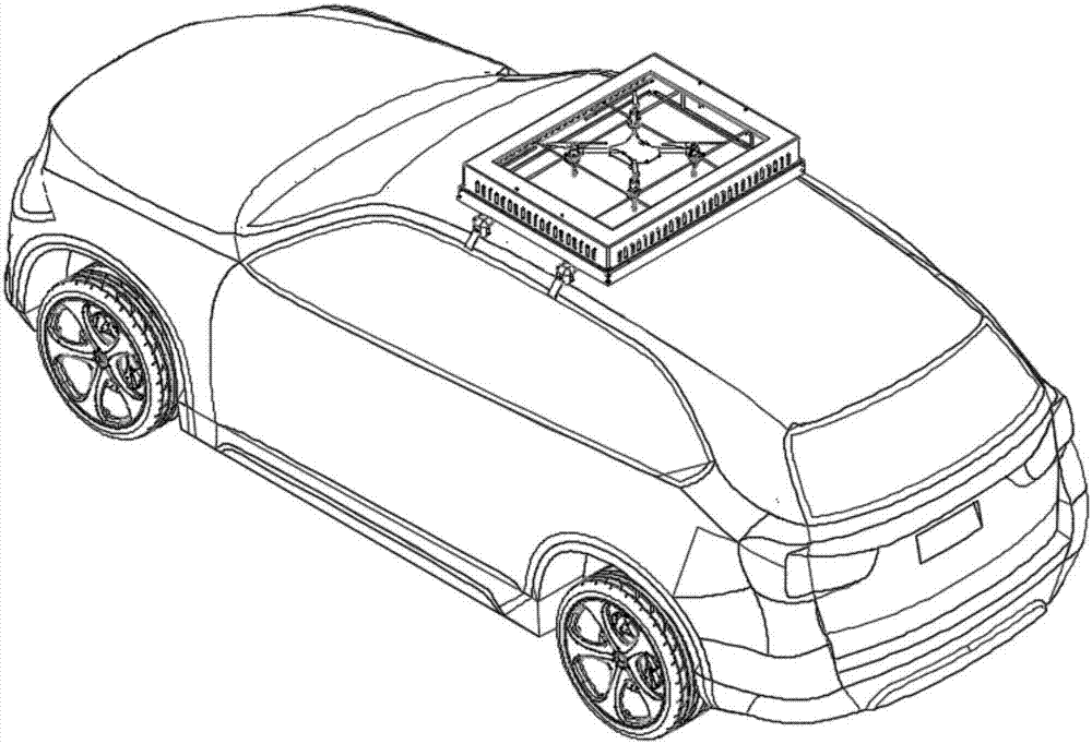
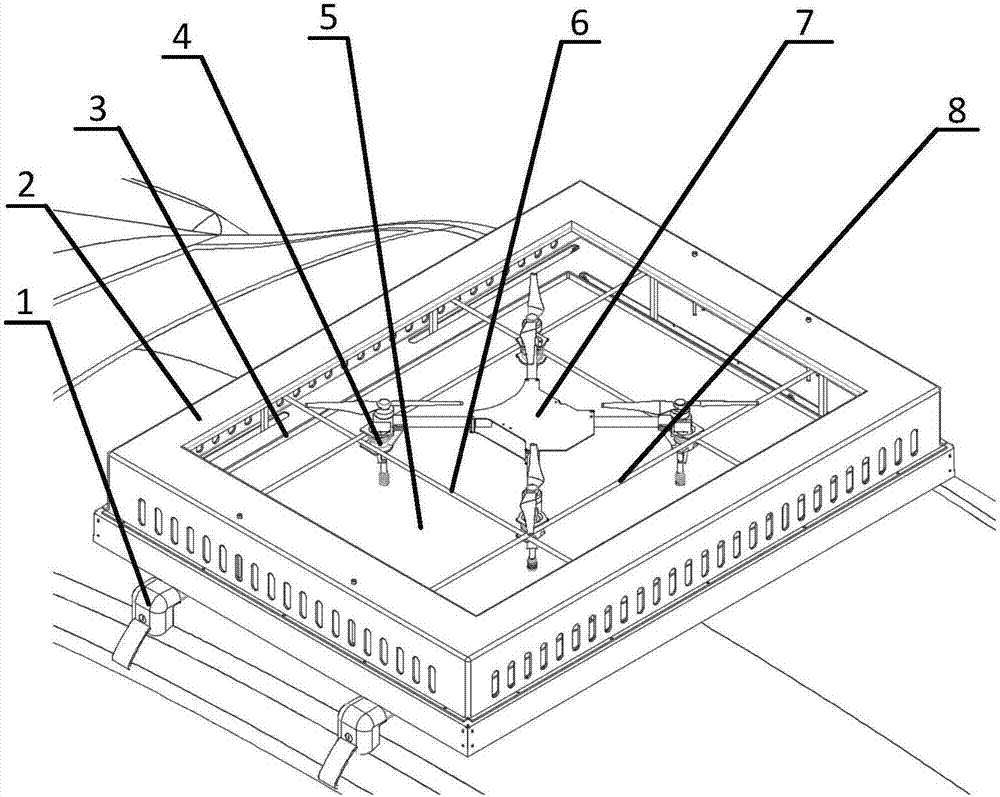
[0038] The invention provides a vehicle-mounted take-off and landing fixed platform for a rotary-wing unmanned aerial vehicle, such as figure 1 , figure 2 As shown, the vehicle-mounted take-off and landing fixed platform of the UAV is composed of a UAV fixture, a clamping rod movement device 10, a fixed beam 11 and a driving mechanism, and the peripheral devices are the UAV 7 and a car;
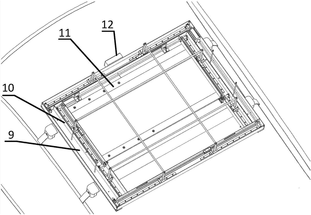
[0039] like Figure 13 As shown, the UAV fixing part is provided with a circumferential groove engaged with the clamp bar; the fixing beam 11 is as Figure 5 As shown, the fixed beam 11 is the skeleton of the entire vehicle-mounted lifting and landing fixed platform, and bears the weight of the entire vehicle-mounted lifting and landing fixed platform. like image 3 , Figure 4 As shown, the fixed beam 11 is fixed on the top of the car through the fixed hole 13 on the luggage rack 1, the clamping rod moving device 10 is installed on the fixed beam 11, and the clamping rod moving device 10 moves under the drive of the driving mechanism to realize the connection with the UAV. The engagement and separation of the circumferential grooves of the fixing parts realizes the fixing and separation of the UAV 7 and the vehicle-mounted take-off and landing fixed platform.
[0040] The clamp bar moving device 10 of the present embodiment is as Figure 7 As shown, the clamp bar moving device 10 includes a clamp bar, a synchronous belt device, a slider guide rail and a U-shaped aluminum fixed frame 9, the slider guide rail and the synchronous belt device are fixed in the U-shaped aluminum fixed frame 9, and the clamp bar is fixed by a support frame On the slider 16 of the slider guide rail, the support frame is clamped and fixed with the synchronous belt device through the entrainment piece 15, the axis direction of the clamping rod is perpendicular to the moving direction of the slider 16, and there are four clamping rods, which are criss-crossed into a well shape , the two clamping rods parallel to each other move towards or back to each other.
[0041] like Figure 7 , Figure 9 As shown, the two ends of the synchronous belt 18 are respectively supported by the synchronous pulley 19 at the end of the stepping motor 30 and the synchronous pulley 19 at the other end. The guide rail 17 is fixed on the U-shaped aluminum, and there are two front and rear guide rails 17, and they are arranged along the front and rear centers. The line is symmetrically distributed, there is a freely movable slider 16 on the guide rail 17, the support seat 14 is fixed on the slider 16, the support frame is fixed on the support seat 14, and the support frame is fixed on the upper and lower ends of the same synchronous belt 18 by the entrainment piece 15 Therefore, when the synchronous belt 18 moves, the support frame can be made to slide on the guide rail 17, and at the same time move closer to or away from the front and rear center line, and the clamp bars are fixed on the support frame, so the two clamp bars parallel to each other move towards or back. The timing belt tensioning clip 20 is fixed on the timing belt 18, which can solve the problem that the timing belt 18 becomes longer after being used for a long time.
[0042] like Image 6 As shown, the U-shaped aluminum fixed frame 9 is composed of six U-shaped aluminums, and is built into a square frame.
[0043] The driving mechanism of the present invention is as Figure 9 As shown, the driving mechanism includes a stepping motor 30 , a transmission shaft 32 and a coupling 31 , and the stepping motor 30 drives the transmission shaft 32 to move through the coupling 31 .
[0044] The vehicle-mounted take-off and landing fixed platform of the UAV adopts a separate control box 12 to control the motion of the driving mechanism. like Figure 16 As shown, the control box 12 includes a wireless receiver 26 , a control chip 27 , a stepper motor driver 28 , a battery 29 , and a transformer module 25 . The battery 29 is responsible for supplying power to the entire vehicle platform, and the transformer module 25 is used to convert the voltage of the battery into the voltage of the control chip 27, thereby supplying power.
[0045] The vehicle-mounted take-off and landing fixed platform of the UAV is provided with a landing platform 5, such as Figure 10 As shown, the landing platform 5 is a box with one end open, and the closed surface corresponding to the opening surface has a long hole; The holes allow the clamping bars to be located above the landing platform 5 . After covering, the gap with the U-shaped aluminum fixed frame 9 is 3mm, and the center of the landing platform 5 is pasted with a two-dimensional code, which is used for the UAV 7 to identify, locate and land.
[0046] The vehicle-mounted platform is open and prone to water accumulation, such as Figure 10 , Figure 11 , Figure 12 As shown, in the present embodiment, a rain cover 2 is provided on the landing platform 5, and a rain-shielding frame 3 is fixed around the landing platform, so that rainwater is blocked in the center of the platform to prevent rainwater from flowing into the inside of the platform; the sealing surface of the landing platform is provided with water leakage Holes 22 flow away rainwater in time.
[0047] For the large amount of high-speed airflow generated during the landing process of the drone, such as Figure 11 As shown, in this embodiment, air guide grooves 23 are processed around the rain cover 2, so that the airflow can be guided away in time to avoid the impact of air backflow on the landing of the UAV 7.
[0048] In this embodiment, considering the space size of the roof, two long clamp bars 8 and two short clamp bars 6 are used for the clamp bars, and one of the clamp bars parallel to the luggage rack 1 is fixed on the support seat 14 through the support frame. Support seat 14 is fixed on U-shaped aluminum by bolt 21 as Figure 8 shown, namely figure 2 The long clamp bar 8 shown, the UAV fixing part Ⅰ 4 is as Figure 14 As shown, it is installed on the four landing legs of the UAV 7, but since one of the long clamping rods 8 is fixed, correspondingly, the groove on the side of the UAV fixing part II24 embedded with the long clamping rod 8 cut flat, such as Figure 15 As shown, it is convenient for the take-off and landing of the UAV 7.
[0049] The wireless receiver 26 receives the take-off or landing signal sent by the UAV 7. After the control chip 27 has processed the received wireless signal, the stepper motor 30 is driven by the stepper motor driver 28 to make the clamping rod moving device 10 move. Thereby releasing or clamping the drone 7 .
[0050] To sum up, the above are only preferred embodiments of the present invention, and are not intended to limit the protection scope of the present invention. Any modifications, equivalent replacements, improvements, etc. made within the spirit and principles of the present invention shall be included within the protection scope of the present invention.

PUM

no PUM

Description & Claims & Application Information

We can also present the details of the Description, Claims and Application information to help users get a comprehensive understanding of the technical details of the patent, such as background art, summary of invention, brief description of drawings, description of embodiments, and other original content. On the other hand, users can also determine the specific scope of protection of the technology through the list of claims; as well as understand the changes in the life cycle of the technology with the presentation of the patent timeline. Login to view more.

Similar technology patents

Classification and recommendation of technical efficacy words

Why Eureka
Try Eureka