Spring type speed limiter tensioning device constant in tensioning force

A tensioning device and tensioning force technology, applied in the field of elevators, can solve problems such as loss of safety barriers, insufficient tensioning force, and affecting the life of steel wire ropes, and achieve the effect of ensuring safe use

Inactive Publication Date: 2017-06-30
NINGBO HONGDA ELEVATOR
View PDF12 Cites 4 Cited by
  • Summary
  • Abstract
  • Description
  • Claims
  • Application Information

AI Technical Summary

Problems solved by technology

[0003] But there is following technical problem in existing spring-type overspeed governor tensioning device: because the wire rope on the tensioning pulley 1a that is installed on the sheave mount 2a can be extended gradually after being affected by factors such as external force, humidity, once the wire rope stretches long, the compression spring 4...

Method used


Image

  • Spring type speed limiter tensioning device constant in tensioning force
  • Spring type speed limiter tensioning device constant in tensioning force
  • Spring type speed limiter tensioning device constant in tensioning force

Examples


Embodiment

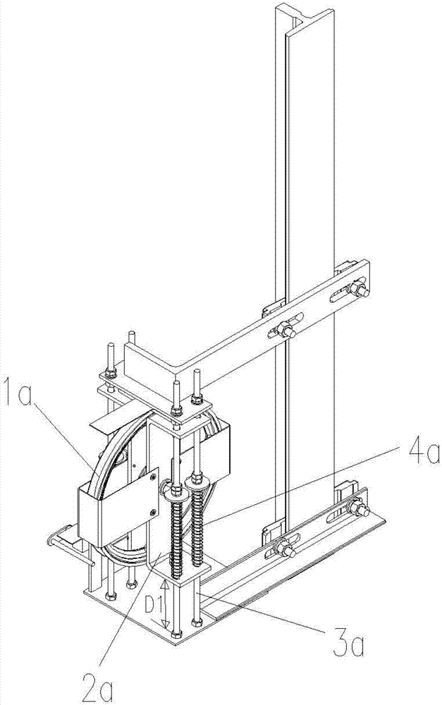
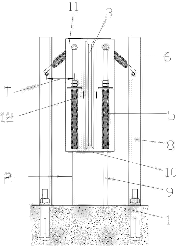
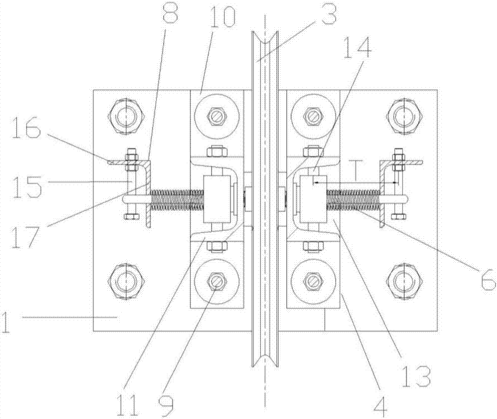
[0030] Such as Figure 2 to Figure 4 As shown, a spring type speed governor tensioning device with constant tension force includes a base 1, a guide assembly 2 fixed on the base 1, and a tensioning device installed on the guide assembly 2 and sliding up and down along the guide assembly 2. The wheel assembly, the tension wheel assembly includes a tension wheel 3, a sheave mounting seat 4, a main compression spring assembly for providing a tension force in the vertical direction for the tension wheel 3, and the base 1 is located on the sheave Both sides of the mounting base 4 are respectively symmetrically provided with two auxiliary compression spring assemblies, and each auxiliary compression spring assembly includes an auxiliary compression spring 6 and is used to adjust the force direction and size of the auxiliary compression spring 6 when the wire rope is elongated. As for the adjustment mechanism, the two secondary compression spring components are respectively connected...


PUM


Abstract

A spring type speed limiter tensioning device constant in tensioning force comprises a base, a guiding assembly fixed to the base, and a tensioning wheel assembly. The tensioning wheel assembly comprises a tensioning wheel, a rope wheel installing base and a main compression spring assembly, and is characterized in that the parts, located on the two sides of the rope wheel installing base, of the base are symmetrically provided with two auxiliary compression spring assemblies; each auxiliary compression spring assembly comprises an auxiliary compression spring and an adjusting mechanism used for adjusting the stress direction and degree of the auxiliary compression spring during stretching of a steel wire rope; the two auxiliary compression spring assemblies are connected with the two sides of the rope wheel installing base correspondingly for compensating for the tensioning force, attenuated in the vertical direction, of the main compression spring assembly along with stretching of the steel wire rope. The spring type speed limiter tensioning device constant in tensioning force can compensate for tensioning force attenuation in the steel wire rope stretching range.

Description

technical field [0001] The invention relates to the technical field of elevators, in particular to a spring-type overspeed governor tensioning device with constant tension force. Background technique [0002] Existing spring-type overspeed governor tensioning device, its structure is as follows figure 1 As shown, it includes a tensioning wheel 1a, a rope wheel mounting seat 2a for installing the tensioning wheel 1a, a guide assembly 3a and a compression spring 4a. The rope wheel mounting seat 2a is installed on the guide assembly 3a and moves up and down along the guide assembly 3a Sliding, one end of the compression spring 4a is fixed on the guide assembly 3a, and the other end abuts against the sheave mounting seat 2a to provide tension in the vertical direction for the sheave mounting seat 2a. [0003] But there is following technical problem in existing spring-type overspeed governor tensioning device: because the wire rope on the tensioning pulley 1a that is installed ...

Claims


Application Information

Patent Timeline
IPC IPC(8): B66B5/04
CPCB66B5/044
Inventor 龚文炜
Owner NINGBO HONGDA ELEVATOR
Why Eureka
Try Eureka