
Wire electrode supply device for wire-cut electric discharge machine

a wire electrode and electric discharge machine technology, applied in the direction of metal-working equipment, manufacturing tools, electrical-based machining equipment, etc., can solve the problems of wire slackening, electrode shift, tension change, etc., to prevent slacking and snapping, prevent slackening of wire electrodes, and simple construction

Inactive Publication Date: 2007-10-04
FANUC LTD
View PDF3 Cites 13 Cited by
  • Summary
  • Abstract
  • Description
  • Claims
  • Application Information

AI Technical Summary

Benefits of technology

[0015]The present invention provides a wire electrode supply device for a wire-cut electric discharge machine that does not require a wire electrode tension detector, and which can prevent slack from occurring in the wire electrode as well as the snapping of the wire electrode even with the use of a heavy wire bobbin and maintain a constant tension on the wire electrode.
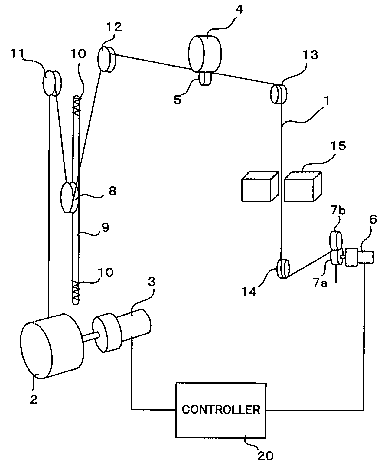
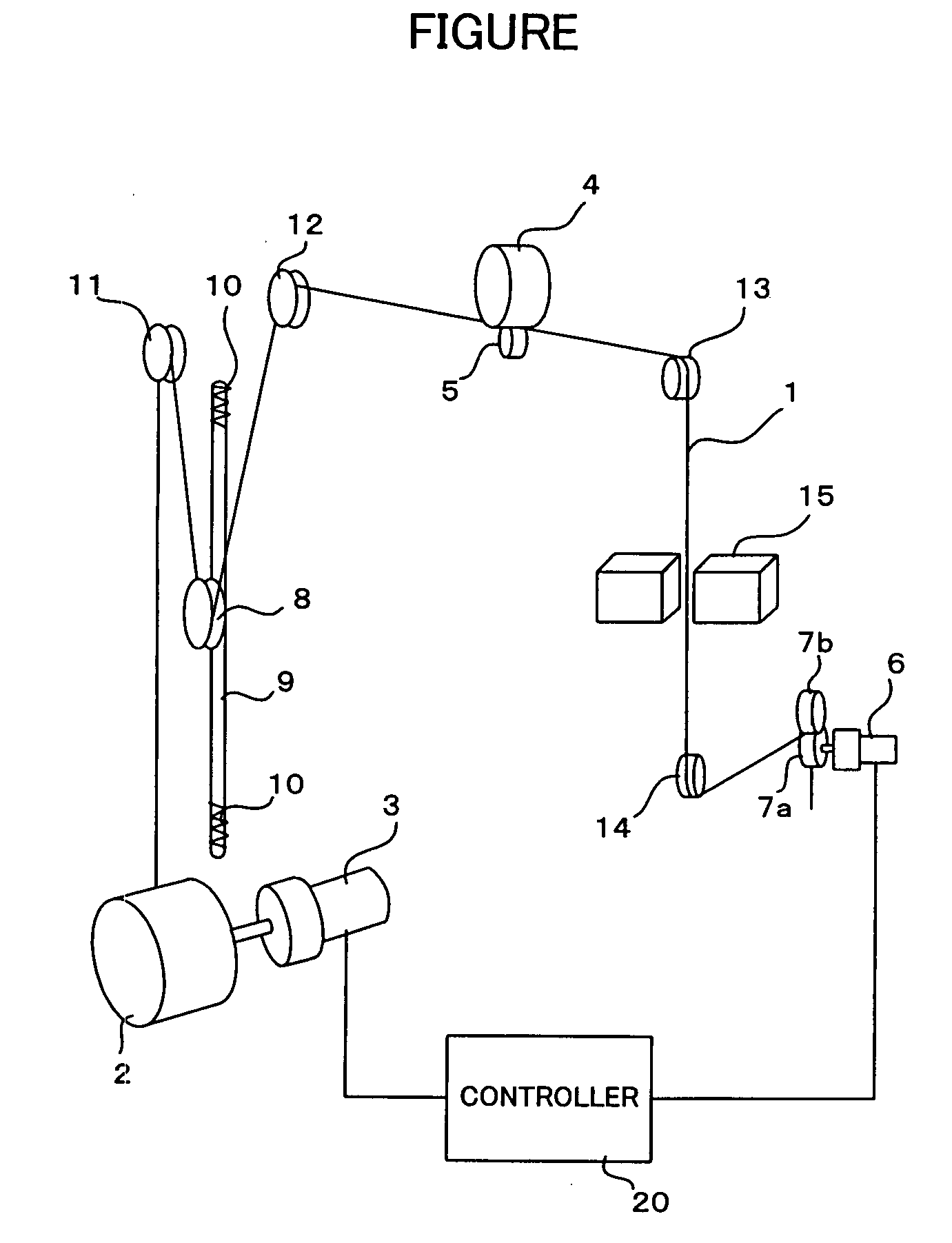
[0016]A wire electrode supply device of the present invention supplies a wire electrode from a wire bobbin to a machining region of a wire-cut electric discharge machine. The wire electrode supply device comprises: a wire winding roller for winding the wire electrode; a brake roller for braking the wire electrode, the wire winding roller and the brake roller being arranged with the machining region in between; a torque motor operatively connected to the wire bobbin, for applying back tension to the wire electrode fed from the wire bobbin; a pulley arranged between the wire bobbin and the brake roller movably to ascend / descend by gravity and wire tension, such that the wire electrode fed from the wire bobbin travels to the brake roller through the pulley; and a controller for reducing the back tension applied by the torque motor for a predetermined period of time when a winding speed of the wire electrode by the wire winding roller is changed from low to high.
[0019]The wire electrode supply device of the present invention does not require a wire electrode tension detector, is of simple construction, and can prevent slack in as well as snapping of the wire electrode even with the use of a heavy wire bobbin and prevent the wire electrode from shifting from its predetermined travel position. Moreover, the wire electrode supply device of the present invention can prevent snapping and slackening of the wire electrode when a torque motor is used and a heavy wire bobbin is used.

Problems solved by technology

As a result, the wire slackens and the tension changes, with the possibility that the wire electrode shifts from a predetermined travel position.
By contrast, when the wire feed speed is changed from slow to fast, the large inertia of the heavy wire bobbin does not track the change in the speed of rotation but lags it instead, and there is a possibility that an excessive load is placed on the wire electrode due to the difference between the winding speed of the wire winding means and the supply speed from the wire bobbin and the wire electrode snaps.
However, a problem with the use of a torque motor to drive the wire bobbin is that it is limited to those cases in which the mass of the wire bobbin is small.
If the wire bobbin is a heavy one, slack in or the snapping of the wire electrode due to the inertia of the heavy wire bobbin cannot be prevented by the back tension of the torque motor alone.
Specifically, when the travel speed of the wire electrode is changed from slow to fast, due to its inertia the heavy wire bobbin remains at slow without switching immediately to fast, which increases the tension on the wire electrode and could cause it to snap.
Moreover, when the travel speed of the wire electrode is changed from fast to slow, again due to its inertia the heavy wire bobbin remains at fast without switching immediately to slow, which causes the wire electrode to slacken and the travel position of the wire electrode to shift, and could cause the wire electrode to slip off the guide rollers altogether.

Method used


Image

  • Wire electrode supply device for wire-cut electric discharge machine
  • Wire electrode supply device for wire-cut electric discharge machine

Examples


Embodiment Construction

[0021]Referring to FIGURE, a wire bobbin 2 on which wire electrode 1 is wound is driven by a torque motor 3. The wire electrode 1 unwound from the wire bobbin 2 passes through a roller 11, around a pulley 8, around a roller 12, between a brake roller 4 and a press roller 5, and further, passes around a roller 13, through a work area in which a workpiece 15 is worked, around a roller 14 and between wire wind-up rollers 7a, 7b driven by a wire wind-up motor 6 so as to be wound up by wire wind-up rollers 7a, 7b. The wire wind-up motor 6, the torque motor 3 and a brake apparatus, not shown, that drives the brake roller 4 are connected to and controlled by a controller 20 that controls the wire-cut electric discharge machine.

[0022]The pulley 8 ascends and descends along guide means 9. Springs 10 are provided at the stroke ends of both the ascending and descending strokes of the pulley 8. The springs 10 function as dampers that absorb the impact when the pulley 8 reaches the end of its st...


PUM

PropertyMeasurementUnit
Forceaaaaaaaaaa
Speedaaaaaaaaaa
Tensionaaaaaaaaaa

Abstract

A wire electrode supply device capable of preventing slack and snapping of a wire electrode even using a heavy wire bobbin without using a wire electrode tension detector. A pulley is provided between the wire bobbin driven by a torque motor and a brake roller. The wire electrode unwinds from the wire bobbin, passes through the pulley, brake roller and a workpiece work area, and is taken up by a wind-up roller. When the wire electrode traveling speed is changed from fast to slow, the pulley descends to prevent the wire electrode from slackening between the wire bobbin and the brake roller. When the traveling speed is changed from slow to fast, the back tension from the torque motor is reduced for a predetermined period of time, reducing tension on the wire electrode and preventing it from snapping. Also, the pulley descends, rotating the wire bobbin in the feeding direction and quickening tracking of the shift to fast feed speed, enabling snapping of the wire electrode to be prevented even when a heavy wire bobbin is used.

Description

BACKGROUND OF THE INVENTION[0001]1. Field of the Invention[0002]The present invention relates to a wire electrode supply device for a wire-cut electric discharge machine.[0003]2. Description of Related Art[0004]A wire electrode supply device for a wire-cut electric discharge machine comprises a wire bobbin that supplies the wire electrode, brake means, and wire winding means. The wire electrode supplied from the wire bobbin is braked by a brake roller of the brake means and passed through a work area where a workpiece is processed, after which the wire is taken up by a wind-up roller or other such wire winding means so that the wire electrode travels while tension is imparted to it. Voltage is then applied between the wire electrode and the workpiece so as to create a discharge and carry out machining.[0005]In the case of a heavy wire electrode, the wire bobbin of the wire electrode supply device also becomes heavy and therefore a DC motor whose speed can be controlled is used for t...

Claims


Application Information

Patent Timeline
IPC IPC(8): B23H7/10
CPCB23H7/105B23H7/104
Inventor KITA, YUKITAKAYAMA, YUSHITAMURA, YOSHIAKI
Owner FANUC LTD
Learn More