Antenna assembly and installation adjustment device thereof

A technology for installation and adjustment of antenna components, applied to antenna supports/mounting devices, antenna components, antennas, etc., can solve the problems of cumbersome installation methods, heavy installation components, and heavy component weight, and achieve light overall weight and simplified processing The effect of process and production cost reduction

Inactive Publication Date: 2017-06-30
TONGYU COMM INC
View PDF5 Cites 10 Cited by
  • Summary
  • Abstract
  • Description
  • Claims
  • Application Information

AI Technical Summary

Problems solved by technology

[0004] At present, most of the installation components of base station antennas on the market use connecting buckles and connecting arms to adjust the pitch attitude of the antenna. Such installation components are relatively bulky and costly. Operation, even some parts need to be disassembled, which not only wastes time, but also requires a lot of manpower
In addition, some macro base station antenna poles are installed using two identical clamping codes and two screw rods are used to lock and connect the clamping method. The antenna pitch attitude adjustment adopts 4-stage steel structure components and half-moon dials. Although this antenna installation method The structural components are strong, but the installation method is also cumbersome, difficult to locate, difficult to install, the components are heavy, the required manpower and material resources are large, and the cost is high

Method used


Image

  • Antenna assembly and installation adjustment device thereof
  • Antenna assembly and installation adjustment device thereof

Examples


Embodiment Construction

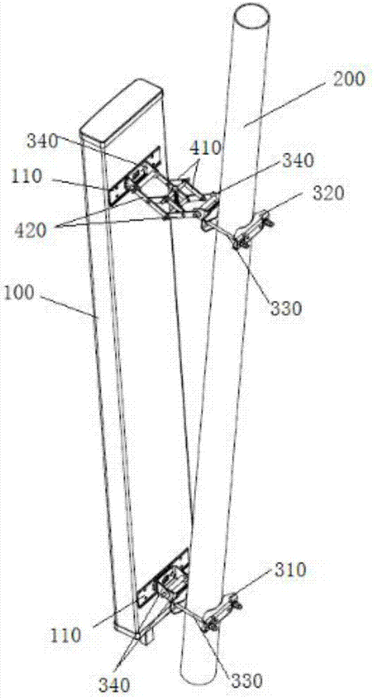
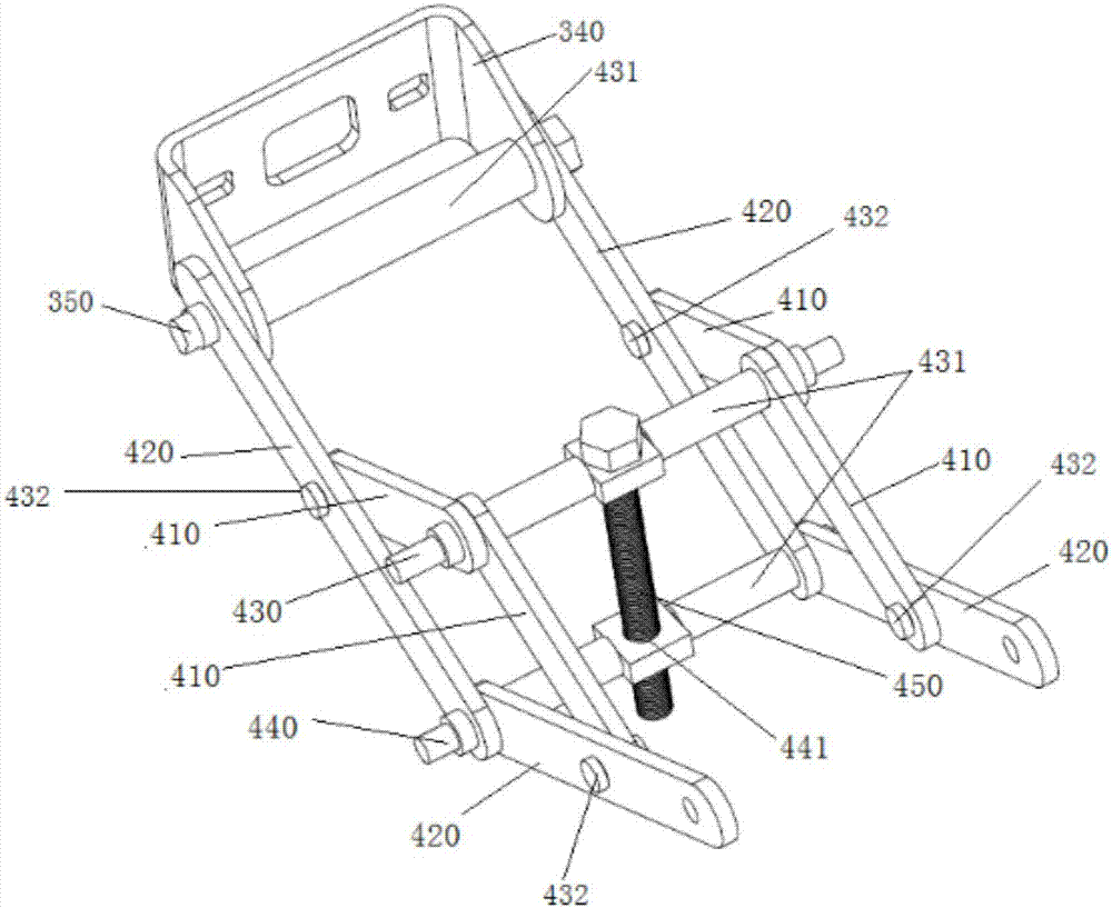
[0027] see figure 1 and figure 2 , in this embodiment, the antenna assembly of the present invention includes the antenna 100 shown in the figure, the pole 200, and the installation adjustment device that connects the antenna and the pole and can adjust the angle of the antenna. The installation adjustment device includes an adjustable parallelogram connecting rod mechanism, and a connection mechanism arranged at both ends of the parallelogram linkage mechanism to connect the antenna 100 and the pole 200, the parallelogram linkage mechanism includes two sets of parallelogram members arranged in parallel, and each parallelogram member includes two A first connecting rod 410 with one end rotatably connected, and two second connecting rods 420 connected with one end relatively rotatable, the two first connecting rods 410 and the two second connecting rods 420 form a parallelogram, and The connecting ends are relatively rotatable connections, the two first connecting rods 410 ar...


PUM


Abstract

The invention provides an antenna assembly and an installation adjustment device for mounting an antenna. The installation adjustment device comprises an adjustable parallelogram link mechanism and connecting mechanisms that are arranged at the two ends of the parallelogram link mechanism and can be connected with an antenna and a holding pole. The parallelogram link mechanism consists of two groups of parallelogram components arranged in parallel; each parallelogram component includes two first connecting rods and two second connecting rods, wherein one end of each first connecting rod can be connected in a relative rotation manner and one end of each second connecting rod can be connected in a relative rotation manner; and the two first connecting rods and the two second connecting rods are connected to form a parallelogram, wherein the connecting ends are connected in a relative rotation manner. A first adjusting rod and a second adjusting rod are connected at the diagonal line in the middle of the two parallelogram components; a first adjusting rod is provided with a first adjusting hole and a second adjusting hole is formed in the second adjusting rod; and a third adjusting rod is inserted between the first adjusting hole and the second adjusting hole. The distance between the first adjusting rod and the second adjusting rod can be adjusted by adjusting the third adjusting rod. Therefore, the antenna pitch attitude adjustment efficiency can be improved substantially and the installation cost can be reduced.

Description

[0001] 【Technical field】 [0002] The invention relates to the communication field, in particular to a base station antenna installation adjustment device. [0003] 【Background technique】 [0004] At present, most of the installation components of base station antennas on the market use connecting buckles and connecting arms to adjust the pitch attitude of the antenna. Such installation components are relatively bulky and costly. The operation even needs to dismantle some parts to realize it, which not only wastes time, but also requires a lot of manpower. In addition, some macro base station antenna poles are installed using two identical clamping codes and two screw rods are used to lock and connect the clamping method. The antenna pitch attitude adjustment adopts 4-stage steel structure components and half-moon dials. Although this antenna installation method The structural components are strong, but the installation method is also cumbersome, difficult to locate, difficult...

Claims


Application Information

Patent Timeline
Patent Type & Authority Applications(China)
IPC IPC(8): H01Q1/12H01Q3/06
CPCH01Q1/1242H01Q3/06
Inventor 王斌钟欢欢成钢吴鹏方铁勇张理栋
Owner TONGYU COMM INC
Why Eureka
Try Eureka