
Rotating Cylinder Device

A rotating drum, cylindrical technology, applied in the field of belt winding mechanism, can solve the problem of uneven pressure around the arm, and achieve the effect of pressure uniformity

Active Publication Date: 2017-07-04
ASIA OPTICAL CO INC +1
View PDF7 Cites 2 Cited by
  • Summary
  • Abstract
  • Description
  • Claims
  • Application Information

AI Technical Summary

Problems solved by technology

[0005] The technical problem to be solved by the present invention is to provide a rotating drum device, aiming at the defect that the sphygmomanometer in the prior art exerts uneven pressure around the arm, the belt body is wound and contracted in a uniform manner, so that the pressure applied to the user's arm Ambient pressure can be more even

Method used


Image

  • Rotating Cylinder Device
  • Rotating Cylinder Device
  • Rotating Cylinder Device

Examples


Embodiment Construction

[0022] In order to make the above objects, features, and advantages of the present invention more comprehensible, preferred embodiments will be described in detail below with accompanying drawings.

[0023] In the embodiments of the present invention described below, the so-called orientations "up", "down", "left", and "right" are only used to indicate the relative positional relationship in the drawings, and are not used to limit the present invention. .

[0024] In addition, it should be understood that components not shown in the drawings or not described in the specification are forms known to those skilled in the art.

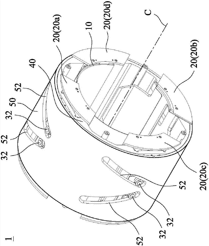
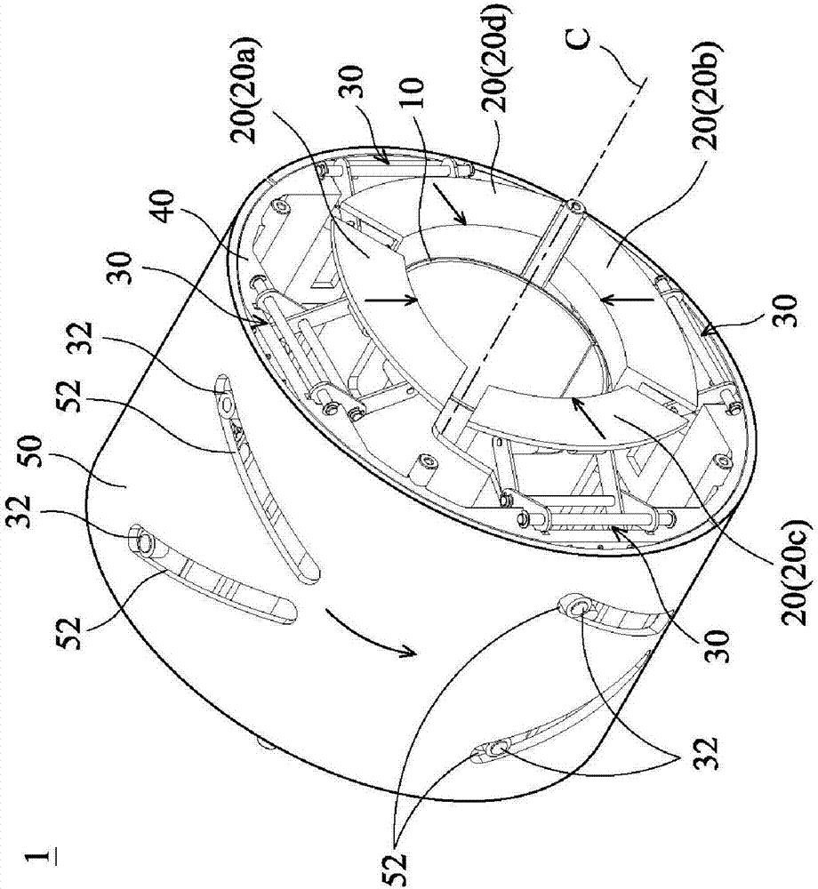
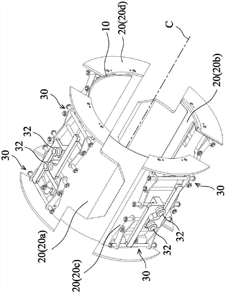
[0025] Please see first Figure 1A , 1B The rotary cylinder device 1 according to one embodiment of the present invention includes a belt body 10, a plurality of plate-shaped parts 20 (including an upper plate-shaped part 20a, a lower plate-shaped part 20b, a left plate-shaped part 20c and a right plate-shaped part 20d), a plurality of A link mechanism 3...


PUM


Abstract

A rotating cylinder device includes a cylindrical belt having an axis line, several plate-shaped parts, several link mechanisms, and a cylindrical casing. The plate-shaped parts are disposed outside the belt and arranged symmetrically across the axis line. The link mechanisms are pivotally connected to the respective plate-shaped parts and one end of each is pivotally connected to one plate-shaped part and the other end has a moving protrusion. The moving protrusions are adapted to move along a first direction parallel to the axis line. The cylindrical casing is adapted to rotate about the axis line and is coupled to the moving protrusions. When the cylindrical casing rotates about the axis line, the moving protrusions are driven to move along the first direction, and the plate-shaped parts are driven by the link mechanisms to move along a second direction perpendicular to the axis line, to contract the belt.

Description

technical field [0001] The present invention relates to a rotating drum device; in particular, it relates to a belt winding mechanism of the rotating drum device. Background technique [0002] A blood pressure monitor is a medical instrument used to measure blood pressure. [0003] In the known sphygmomanometer, when the user wraps the cuff on the measurement site (such as the arm), pressurizes the pressure in the cuff to higher than the maximum blood pressure, and then gradually reduces the pressure in the cuff, the pressure sensor is used to transmit the pressure. The pulsation in the artery is detected through the armband, and then the maximum blood pressure and the minimum blood pressure are determined using the established calculation method. [0004] However, the known sphygmomanometer has the problem of uneven pressure applied around the arm in the design of the pressurized (i.e. contracted) armband, which not only affects the operating comfort of the user, but also ...

Claims


Application Information

Patent Timeline
Patent Type & Authority Applications(China)
IPC IPC(8): A61B5/022A61B90/00
CPCA61B5/02141A61B5/02233A61B5/702F16H19/001F16H21/54F16H25/18F16H37/12
Inventor 土屋睦志今井直史
Owner ASIA OPTICAL CO INC
Learn More