Hybrid vehicle and method of braking hybrid vehicle

a hybrid vehicle and hybrid technology, applied in the direction of electric devices, battery/fuel cell control arrangement, electric control, etc., can solve the problems of reduced engine loss, inability to regenerative braking, so as to reduce the electric power input to the power storage, suppress the overcharging of the power storage, and achieve the effect of large braking force applied by the engine brak

Active Publication Date: 2021-06-01
TOYOTA JIDOSHA KK
View PDF6 Cites 2 Cited by
  • Summary
  • Abstract
  • Description
  • Claims
  • Application Information

AI Technical Summary

Benefits of technology

[0009]The present disclosure was made to solve the problem above, and an object thereof is to provide a hybrid vehicle that readily ensures sufficient braking force by engine brake during deceleration of the vehicle and a method of braking a hybrid vehicle.
[0012]Furthermore, when the second condition in addition to the first condition is satisfied, the controller of the hybrid vehicle performs the previously-described motoring by setting throttle opening to first opening or larger and setting WGV opening to second opening or smaller (which is also referred to as a “turbocharged valve state” below). With the throttle opening being large and the WGV opening being small, forced induction by the turbocharger is performed and charging efficiency (that is, suction efficiency) of the engine and a back pressure of the engine (that is, a pressure on an exhaust side) both become higher. In the engine, as charging efficiency is higher, compression work tends to be greater, and as the back pressure is higher, exhaust loss tends to be larger. Therefore, when both of the first condition and the second condition are satisfied during deceleration of the vehicle and when the previously-described motoring is performed in the turbocharged valve state, resistance of the engine becomes higher and braking force applied by engine brake becomes stronger. Thus, in the hybrid vehicle, sufficient braking force is readily ensured by engine brake during deceleration of the vehicle.
[0020]In the turbocharged valve state, the throttle valve may fully be opened and the WGV may fully be closed. In other words, a fully opened state may be defined as first opening and a fully closed state may be defined as second opening. According to such a configuration, when the second condition in addition to the first condition is satisfied, large braking force applied by engine brake is readily obtained.
[0021]The hybrid vehicle may include a power storage capable of input and output of electric power to and from each of the MG1 and the MG2. According to such a configuration, electric power generated by each of the MG1 and the MG2 can be input to the power storage. The MG1 and the MG2 may supply and receive electric power to and from each other. According to such a configuration, the controller controls the MG2 to apply regenerative braking so that electric power generated by regenerative braking can be supplied to the MG1 and consumed in motoring by the MG1. As electric power generated by regenerative braking is consumed, electric power input to the power storage is reduced and hence overcharging of the power storage is suppressed.
[0023]The hybrid vehicle may include the electronically controllable brake apparatus. When the first condition is satisfied and the second condition is not satisfied during traveling of the hybrid vehicle, the controller may make braking force applied by the electronically controllable brake apparatus larger than when the second condition is satisfied. When both of the first condition and the second condition are satisfied, such a controller of the hybrid vehicle reinforces braking force applied by engine brake by setting the throttle valve and the WGV to the turbocharged valve state, whereas when only the first condition is satisfied (that is, when the second condition is not satisfied), it makes braking force applied by the electronically controllable brake apparatus larger instead of setting the throttle valve and the WGV to the turbocharged valve state. By doing so, insufficiency in braking force applied by engine brake can be compensated for by the electronically controllable brake apparatus. According to the configuration, regardless of an operation of the brake by the driver, variation in braking force depending on whether or not the second condition is satisfied can be suppressed. Thus, the driver is less likely to feel discomfort during deceleration of the hybrid vehicle. Making braking force applied by the electronically controllable brake apparatus larger includes setting the electronically controllable brake apparatus from an off state to an on state.

Problems solved by technology

For example, when the power storage is fully charged, electric power generated by regenerative braking can no longer be input to the power storage.
In such a situation that electric power generated by regenerative braking cannot be stored nor consumed, regenerative braking cannot be effected.
In such a turbocharged downsizing engine, loss in the engine is lessened by downsizing and braking force by engine brake is weakened.
Therefore, even though fuel to the engine is cut off during deceleration of the vehicle, sufficient braking force by engine brake may not be obtained.
In the engine, as charging efficiency is higher, compression work tends to be greater, and as the back pressure is higher, exhaust loss tends to be larger.

Method used


Image

  • Hybrid vehicle and method of braking hybrid vehicle
  • Hybrid vehicle and method of braking hybrid vehicle
  • Hybrid vehicle and method of braking hybrid vehicle

Examples


Embodiment Construction

[0045]An embodiment of the present disclosure will be described in detail below with reference to the drawings. The same or corresponding elements in the drawings have the same reference characters allotted and description thereof will not be repeated. An electronic control unit is also referred to as an “ECU” below. A hybrid vehicle is also referred to as an “HV” and an electric vehicle is also referred to as an “EV”.

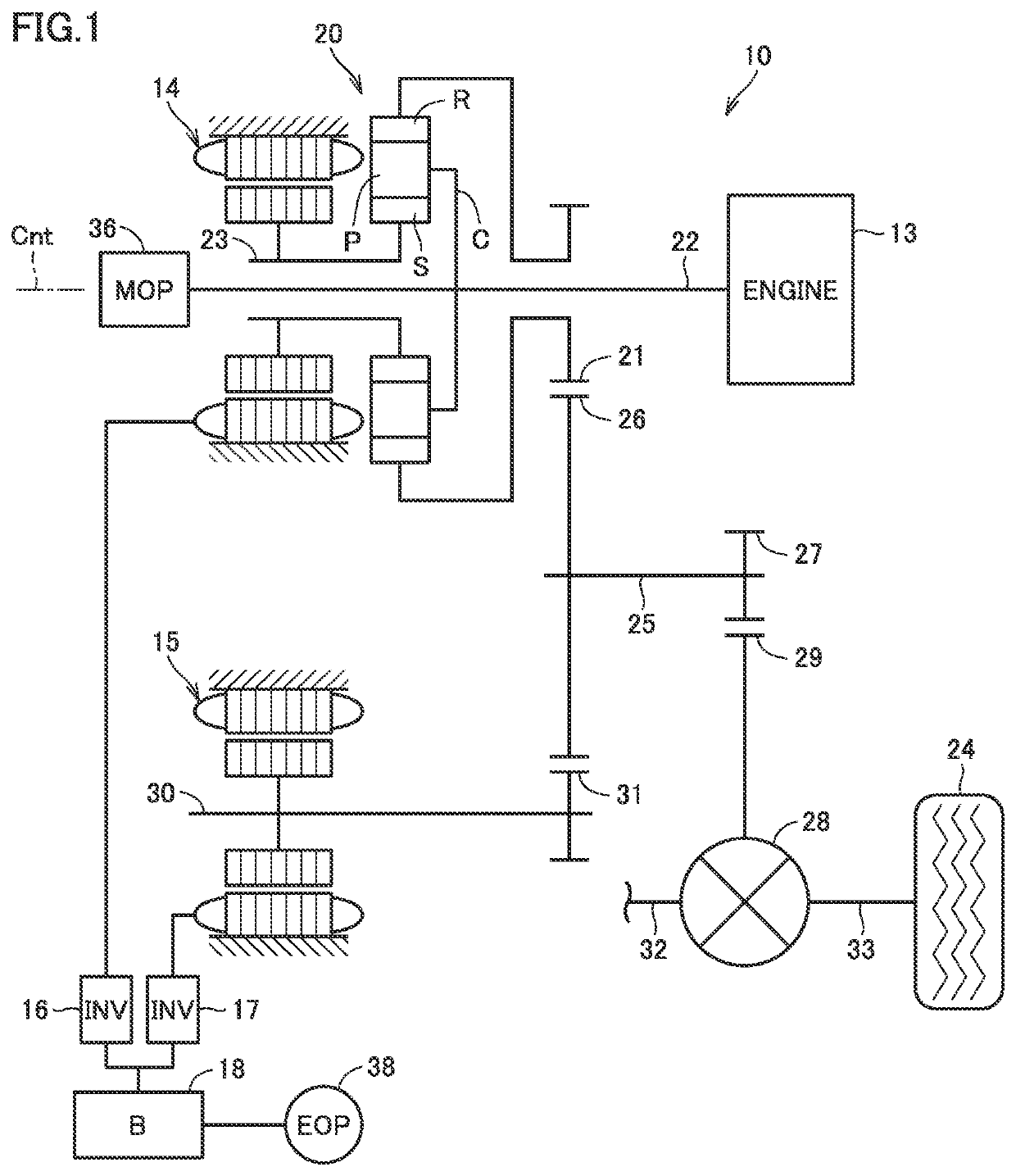
[0046]FIG. 1 is a diagram showing a drive device of a hybrid vehicle according to this embodiment. Though a front-wheel drive four-wheel hybrid vehicle is assumed in the embodiment, the number of wheels and a drive scheme can be modified as appropriate.

[0047]Referring to FIG. 1, a drive device 10 of the hybrid vehicle (which is also simply referred to as a “vehicle” below) includes an engine 13 and motor generators (MGs) 14 and 15 as sources of motive power for traveling. Each of MGs 14 and 15 is a motor generator that performs both of a function as a motor that output...


PUM


Abstract

In a hybrid vehicle, each of an engine and an MG1 is mechanically coupled to a drive wheel with a planetary gear being interposed. The planetary gear and an MG2 are configured such that motive power output from the planetary gear and motive power output from the MG2 are transmitted to the drive wheel as being combined. When a first condition is satisfied during traveling of the vehicle, a controller stops combustion in the engine and performs motoring by the MG1 such that the planetary gear outputs deceleration torque. When a second condition in addition to the first condition is satisfied (YES in S20) during deceleration of the hybrid vehicle with deceleration torque, the controller performs motoring with throttle opening being set to first opening or larger and WGV opening being set to second opening or smaller.

Description

[0001]This nonprovisional application is based on Japanese Patent Application No. 2019-054657 filed with the Japan Patent Office on Mar. 22, 2019, the entire contents of which are hereby incorporated by reference.BACKGROUNDField[0002]The present disclosure relates to a hybrid vehicle and a method of braking a hybrid vehicle.Description of the Background Art[0003]Japanese Patent Laying-Open No. 2015-58924 discloses a hybrid vehicle including an engine with a turbocharger and a motor generator.SUMMARY[0004]A hybrid vehicle is mainly braked by regenerative braking applied by a motor generator, engine brake applied by an engine, and a brake apparatus.[0005]Regenerative braking refers to electric braking applied by converting kinetic energy of a vehicle into electric energy by controlling a motor generator to function as a generator. Electric power generated by regenerative braking can be stored in a power storage mounted on the vehicle. Regenerative braking, on the other hand, is restri...

Claims


Application Information

Patent Timeline
Patent Type & Authority Patents(United States)
IPC IPC(8): B60W30/18B60K6/365B60W10/08B60W10/196B60K6/28B60L7/26B60W10/06B60W10/184B60W10/26B60W20/00B60K6/24
CPCB60W30/18127B60K6/24B60K6/28B60K6/365B60L7/26B60W10/06B60W10/08B60W10/184B60W10/196B60W10/26B60W20/00B60W30/18136B60W2510/0638B60W2510/244B60W2540/10B60W2540/12B60W2710/06B60W2710/08B60W2710/18B60Y2200/92F02D29/02F02D41/0007F02D41/042F02D23/02F02B37/183B60W20/14B60W20/15B60W2510/069F02D2200/101B60L15/2009B60L58/15B60L7/18B60L2220/42B60L50/16B60L2240/441B60L2240/443B60L2240/421B60L2240/423B60L2240/12B60K6/445B60W2710/0638B60W2710/0605B60Y2400/435Y02T10/40Y02T10/64Y02T10/70Y02T10/72
Inventor YONEZAWA, KOICHIYOSHIZAKI, SATOSHIMAEDA, OSAMUANDO, DAIGOASAMI, YOSHIKAZUITAGAKI, KENJIOYAMA, SHUNSUKEMUTA, KOICHIRO
Owner TOYOTA JIDOSHA KK
Why Eureka
Try Eureka