Multifunctional valve

A multi-functional, valve technology, applied in the direction of multi-way valves, valve details, valve devices, etc., can solve the problems of complex structure, automatic control, automatic stop or automatic diversion, etc., and achieve the effect of increasing the perfusion speed

Inactive Publication Date: 2017-07-04
秦朝东
View PDF0 Cites 2 Cited by
  • Summary
  • Abstract
  • Description
  • Claims
  • Application Information

AI Technical Summary

Problems solved by technology

At present, there is no such special valve. In practice, most of them are realized by constant pressure components or devices. Either the structure is complicated, or it cannot automatically control the automatic stop or automatic diversion to another pipeline after the pressure in each distribution pipeline reaches the standard. to go

Method used


Image

  • Multifunctional valve
  • Multifunctional valve

Examples


Embodiment Construction

[0015] The implementation of the present invention will be illustrated by specific specific examples below, and those skilled in the art can easily understand other advantages and effects of the present invention from the contents disclosed in this specification.

[0016] Below in conjunction with accompanying drawing and embodiment the present invention will be further described:

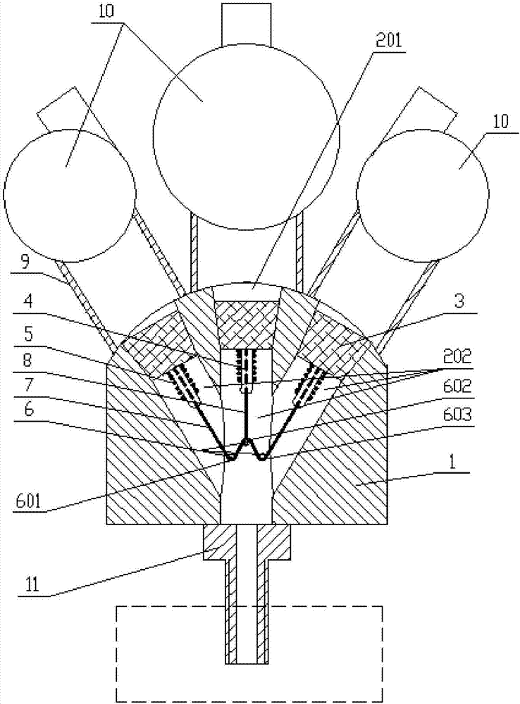
[0017] Such as figure 1 As shown, a multifunctional valve includes a valve body 1, and the valve body 1 is provided with three flow channels 2 with the same diameter, and each flow channel 2 includes a conical hole 201 and a cylindrical hole 202 from top to bottom, The conical hole 201 and the cylindrical hole 202 are coaxially connected, and the small end surface of the conical hole 201 is connected to the top of the cylindrical hole 202, one of the flow channels 2 is located on the axis of the valve body 1, and the other two flow channels 2 is symmetrical about the flow channel 2 on the axis, an...


PUM


Abstract

The invention discloses a multifunctional valve. Three communicated flow passages are arranged in a valve main body of the multifunctional valve; each flow passage comprises a conical hole and a cylindrical hole, wherein one flow passage is positioned on the axial line of the valve main body; the other two flow passages are in bilateral symmetry by using the flow passage positioned on the axial line as the symmetry axis; an identical conical piston is arranged in each flow passage; a fixing rod is arranged in the cylindrical hole; a spring sleeves a rod body at the section, coaxial with the cylindrical hole, of the fixing rod; the upper end of the spring is connected with the piston; the other end of the spring is welded at the surface of the fixing rod; three pulleys are arranged in the flow passage at the crossed and converged part of the three flow passages; a first elastic rope bypasses the three pulleys; the middle is connected with a second elastic rope connected with the small end surface of the piston positioned in the middle; in a natural state, the first elastic rope and the second elastic rope freely and straightly extend. The multifunctional valve has the advantages that the pressure intensity of each container after the filling can be enabled to be maintained in the identical range; the automatic regulation and flow division can also be realized; the filling efficiency is accelerated.

Description

technical field [0001] The invention belongs to the technical field of fluid control, and in particular relates to a valve. Background technique [0002] In industrial production or engineering applications, it is often encountered that multiple containers are filled with the same amount of fluid, and no matter how much the container is filled, the pressure in the container after filling should be kept within a certain range. Especially for gas. At present, there is no such special valve. In practice, most of them are realized by constant pressure components or devices. Either the structure is complex, or it cannot automatically control the automatic stop or automatic diversion to another pipeline after the pressure in each distribution pipeline reaches the standard. to go. Contents of the invention [0003] The purpose of the present invention is to solve the above technical problems and provide a multi-functional valve, which can not only ensure that the pressure of ea...

Claims


Application Information

Patent Timeline
Patent Type & Authority Applications(China)
IPC IPC(8): F16K11/16F16K31/122F16K31/46B67C3/28
CPCF16K11/161B67C3/28F16K31/1225F16K31/465
Inventor 秦朝东
Owner 秦朝东
Why Eureka
Try Eureka