Seeding device

A sowing device and a technology of a seeding port, which is applied to the parts of a seeder, manual sowing tools, etc., can solve the problems of not being able to sow seeds with a large difference in seed size at the same time, poor use effect, and poor stability of the cable drive mode. Achieve the effect of convenient operation, high seeding precision and good stability

Active Publication Date: 2017-07-07
临沂罗开建设工程有限公司
View PDF4 Cites 10 Cited by
  • Summary
  • Abstract
  • Description
  • Claims
  • Application Information

AI Technical Summary

Problems solved by technology

[0004] There is a hand-held sowing device in the existing market, which can only be used for sowing the seeds of a specific plant, and cannot be suitable for sowing seeds with a large difference in grain size at the same time; and the sowing duckbill in the existing sowing device such as Figure 8 As shown, it includes two hollow cones, the two cones are hinged at the discharge port of the sowing device. When in use, the two cones are pressed down to break the soil, and then the two cones are separated by pulling the cable The cone is used to realize the seeds entering the soil between the two cones. The stability of the cable driving mode of the cone of this structure is poor, and the two cones are both hollow and hinged at the discharge port of the sowing device. After pulling the cable 800 to separate the two cones, an open blanking space is formed between the two hollow cones, between the cone and the discharge port, so the seeds often leak out from the outside of the cone without directly Falling between two cones, its use effect is poor

Method used


Image

  • Seeding device
  • Seeding device
  • Seeding device

Examples


Embodiment Construction

[0031] The present invention will be further described below in conjunction with the accompanying drawings.

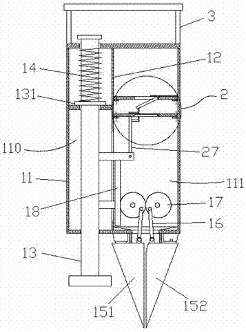
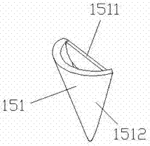
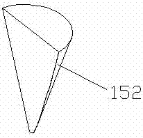
[0032] Such as figure 1 As shown, a sowing device of the present invention includes a housing 11, a first partition 12, a pressing rod 13, a spring 14, a seeding nozzle 151, a soil block 152, a first connecting rod 16, a gear 17, and a rack 18 And the seeding mechanism 2, the first partition 12 is located in the housing 11, and the inner cavity of the housing 11 is divided into an installation chamber 110 and a seeding chamber 111, and the bottom of the housing 11 is provided with the seeding chamber 111 through the discharge port, the seed nozzle 151 is fixed on the discharge port, the earth block 152 is hinged on the side wall of the discharge port, and the two gears 17 are rotated in the seed discharge chamber 111, and the two are meshed with each other. The upper end of the first connecting rod 16 is respectively hinged on the two gears 17, and the lower end is r...


PUM


Abstract

The invention discloses a seeding device, which comprises a shell, a first partition plate, a pressure bar, a spring, a sowing nozzle, a soil poking block, first connecting rods, gears, a rack and a seed metering mechanism. The first partition plate is disposed in the shell, and divides the inner cavity of the shell into an installation cavity and a seed metering cavity, the sowing nozzle is fixed on a discharge port, the soil poking block is hinged to a discharge port side wall, the two gears are rotatably disposed in the seed metering cavity and are engaged with each other, the upper ends of the two first connecting rods are respectively hinged to the two gears, the lower ends are respectively hinged to the sowing nozzle and the soil poking block correspondingly, the pressure bar is movably inserted into the installation cavity, and the upper end and lower end of the pressure bar both pass through the side wall of the shell and extend out of the shell, the spring sleeves the pressure bar, and the upper end and lower end of the spring respectively abut against the inner wall of the installation cavity and the pressure bar correspondingly, the rack is fixed on the pressure bar, and is engaged with one of the gears, the seed metering mechanism is disposed in the seed metering cavity, and one end of the seed metering mechanism is connected to the pressure bar. The seeding device provided by the invention has the advantages of wide applicability and good stability.

Description

[0001] Technical field: [0002] The invention relates to a sowing device. [0003] Background technique: [0004] There is a hand-held sowing device in the existing market, which can only be used for sowing the seeds of a specific plant, and cannot be suitable for sowing seeds with a large difference in grain size at the same time; and the sowing duckbill in the existing sowing device such as Figure 8 As shown, it includes two hollow cones, the two cones are hinged at the discharge port of the sowing device. When in use, the two cones are pressed down to break the soil, and then the two cones are separated by pulling the cable The cone is used to realize the seeds entering the soil between the two cones. The stability of the cable driving mode of the cone of this structure is poor, and the two cones are both hollow and hinged at the discharge port of the sowing device. After pulling the cable 800 to separate the two cones, an open blanking space is formed between the two ho...

Claims


Application Information

Patent Timeline
Patent Type & Authority Applications(China)
IPC IPC(8): A01C7/02A01C7/20
CPCA01C7/02A01C7/20
Inventor 步明玉步小燕步明富
Owner 临沂罗开建设工程有限公司
Why Eureka
Try Eureka