High-efficiency cutting machine for sheet cutting

A cutting machine and high-efficiency technology, applied in metal processing and other directions, can solve the problems of unstable product quality, long lateral movement distance, inaccurate processing stations, etc., and achieve the effect of wide range of use, convenient operation and smooth operation.

Active Publication Date: 2018-05-25
YANCHENG HUASEN MACHINERY
View PDF5 Cites 0 Cited by
  • Summary
  • Abstract
  • Description
  • Claims
  • Application Information

AI Technical Summary

Problems solved by technology

[0002] In industries such as shoemaking, clothing, toys, and home textiles, a cutting machine is an indispensable piece of equipment. A cutting machine is a machine that uses the force of machine movement to pressurize a knife die to cut and process materials. The knife mold of the machine is generally fixedly installed on the punching head, and can only be cut at the fixed position. The knife mold cannot be changed. If there are different types of knife discs that need to be replaced, the operator needs to manually replace each action. , debugging the position and angle, wasting too much time, and the work intensity is high. With the development of society, customers now require small batches and multiple varieties, so it is necessary to constantly replace the cutting die to meet customer needs. The current cutting machine With the technological innovation, the knife mold can be replaced by the rack and pinion mechanism, which improves the work efficiency and reduces the work intensity, but the existing knife mold change mechanism has several defects: 1. The knife mold change mechanism is on the side of the cutting machine , large footprint, long lateral movement distance, and unstable structure; 2. Before changing the tool mold, the working panel needs to be rotated 90°, and the knife mold must be turned horizontally to change the tool. The structure is complex and prone to failure; 3. The existing die changing mechanism is a rack and pinion mechanism, which has a complex structure and troublesome maintenance. 4. After the die is replaced, there will be displacement during the movement or rotation, resulting in inaccurate processing positions and unstable product quality. Improvements to existing structures

Method used


Image

  • High-efficiency cutting machine for sheet cutting
  • High-efficiency cutting machine for sheet cutting
  • High-efficiency cutting machine for sheet cutting

Examples


Embodiment Construction

[0032] The present invention will be further explained below in conjunction with the accompanying drawings and specific embodiments. It should be understood that the following specific embodiments are only used to illustrate the present invention and are not intended to limit the scope of the present invention. It should be noted that the words "front", "rear", "left", "right", "upper" and "lower" used in the following description refer to the directions in the drawings, and the words "inner" and "outer ” refer to directions towards or away from the geometric center of a particular part, respectively.

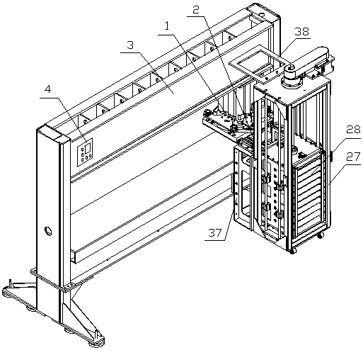
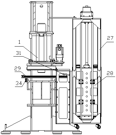
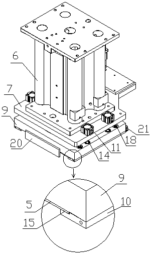
[0033] As shown in the figure, a high-efficiency cutting machine for sheet material cutting according to the present invention includes a punching head 1, a tool changing mechanism 2, a knife magazine 28, a frame 3, a bracket 27, and a control box 4. The cutting head 1 is arranged on the frame 3, the bracket 27 is arranged at one end of the punching head 1, the knife magazine 2...


PUM


Abstract

Disclosed is a highly efficient cutting machine for cutting a sheet, comprising a punching and cutting head (1), a cutting die replacement mechanism (2), a cutter bank (28), a rack (3), a support (27) and a control box (4), wherein the punching and cutting head is arranged on the rack; the support is arranged on an end of the punching and cutting head; the cutter bank is arranged in the support; the cutting die replacement mechanism is arranged between the cutter bank and the punching and cutting head; a cutting die (5) is provided below the punching and cutting head; and the control box is arranged on the rack. The cutting machine is capable of conveniently and automatically replacing a cutting die; the punching and cutting head is capable of punching and cutting a material multiple times from various angles; the location of the cutter bank is scientific and rational; positioning is more precise, the transmission positioning of the cutting die replacement mechanism is precise, the carrying of force is rational, and a service life is prolonged; and the structure of the whole machine is compact, thereby reducing the occupied usage area, and making operation more convenient and allowing for a high working efficiency.

Description

technical field [0001] The invention belongs to the technical field of cutting machines, and in particular relates to a high-efficiency cutting machine for cutting sheets. Background technique [0002] In industries such as shoemaking, clothing, toys, and home textiles, a cutting machine is an indispensable piece of equipment. A cutting machine is a machine that uses the force of machine movement to pressurize a knife die to cut and process materials. The knife mold of the machine is generally fixedly installed on the punching head, and can only be cut at the fixed position. The knife mold cannot be changed. If there are different types of knife discs that need to be replaced, the operator needs to manually replace each action. , debugging the position and angle, wasting too much time, and the work intensity is high. With the development of society, customers now require small batches and multiple varieties, so it is necessary to constantly replace the cutting die to meet cu...

Claims


Application Information

Patent Timeline
Patent Type & Authority Patents(China)
IPC IPC(8): B26F1/38B26F1/44
CPCB26F1/38B26F1/44
Inventor 蔡国靖韦杰韦金权
Owner YANCHENG HUASEN MACHINERY
Why Eureka
Try Eureka