Guide ring structure of low-pressure exhaust cylinder of steam turbine

A deflector ring and exhaust cylinder technology, which is applied in mechanical equipment, engine components, machines/engines, etc., can solve the problem of not considering the aerodynamic performance of the deflector ring contour line, and the inability to use mainstream steam to effectively and reliably guide etc. problems, to ensure aerodynamic performance, reduce total pressure loss, and enhance reliability

Pending Publication Date: 2017-07-07
DONGFANG TURBINE CO LTD
View PDF5 Cites 1 Cited by
  • Summary
  • Abstract
  • Description
  • Claims
  • Application Information

AI Technical Summary

Problems solved by technology

However, so far, no such research results have been made public in the industry; although the Chinese patent literature discloses a technology that opens a gap at the edge of the exhaust end of the guide ring, the name is "steam turbine exhaust diffuser diversion structure". and steam turbine" (public number: CN104533548, public date: April 22, 2015), but the notch structure of the exhaust end of the diversion ring disclosed in this technology is only used for the convenient loading and unloading

Method used


Image

  • Guide ring structure of low-pressure exhaust cylinder of steam turbine
  • Guide ring structure of low-pressure exhaust cylinder of steam turbine
  • Guide ring structure of low-pressure exhaust cylinder of steam turbine

Examples


Embodiment 1

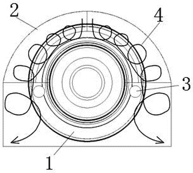
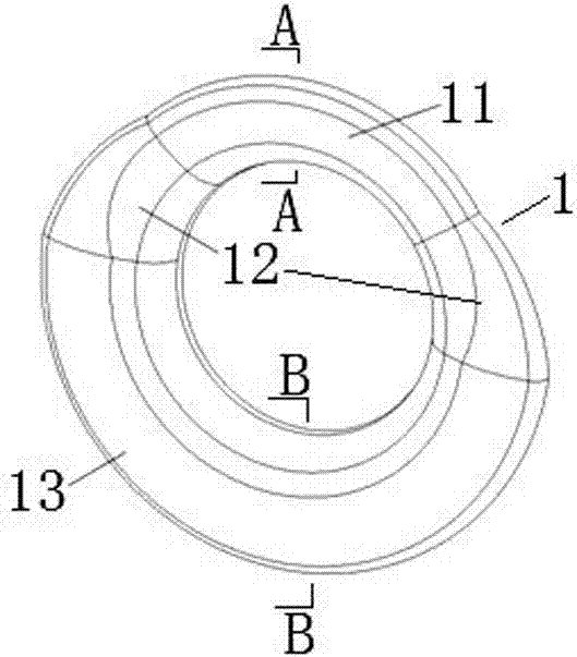
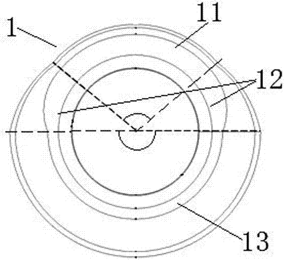
[0029] see Figure 2 to Figure 5 As shown, the present invention includes a guide ring body 1 with a trumpet-shaped structure, and the guide ring body 1 is applied to a steam turbine low-pressure exhaust cylinder with a downward exhaust steam structure.

[0030]The diversion ring body 1 is divided into a top arc section 11 and a bottom arc section 13 in the circumferential direction according to the movement sequence of the vortex formed by the exhaust steam during service, and there is a side part between the top arc section 11 and the bottom arc section 13 The arc section 12 , that is, the side arc section 12 is divided into two sections, which are located at the joints of the top arc section 11 and the bottom arc section 13 . Wherein, the included angle of the center of the top arc 11 is about 90°, the included angle of the center of the bottom arc 13 is about 180°, and the included angle of the center of each side arc 12 is about 45°.

[0031] The guide ring body 1 is com...

Embodiment 2

[0035] see Figure 7 As shown, the present invention includes a guide ring body 1 with a trumpet-shaped structure, and the guide ring body 1 is applied to a steam turbine low-pressure exhaust cylinder with a downward exhaust steam structure.

[0036] The guide ring body 1 is divided into a top arc segment 11 and a bottom arc segment 13 in the circumferential direction according to the movement sequence of the vortex formed by the exhaust steam during service. Wherein, the included angle of the center of the top arc 11 is about 120°, and the included angle of the center of the bottom arc 13 is about 240°, that is, the top arc 11 and the bottom arc 13 form a complete 360° circle in the circumferential direction.

[0037] The diversion ring body 1 is composed of several circumferential sections sequentially superimposed according to the designed circumferential track in its circumferential direction, that is to say, the top arc section 11 and the bottom arc section 13 of the dive...

Embodiment 3

[0040] The invention includes a diversion ring body with a trumpet-shaped structure, and the diversion ring body is applied to a steam turbine low-pressure exhaust cylinder with a downward exhaust steam structure.

[0041] According to the movement sequence of the vortex formed by the exhaust steam during the service process, the diversion ring body is divided into a top arc segment and a bottom arc segment in the circumferential direction. Wherein, the included angle of the center of the top arc is about 100°, and the included angle of the center of the bottom arc is about 260°, that is, the top arc and the bottom arc form a complete 360° circle in the circumferential direction.

[0042] The diversion ring body is composed of several circumferential sections sequentially stacked according to the designed circumferential trajectory in its circumferential direction, that is to say, the top arc section and the bottom arc section of the diversion ring body respectively have circum...


PUM

PropertyMeasurementUnit
Center angleaaaaaaaaaa

Abstract

The invention discloses a guide ring structure of a low-pressure exhaust cylinder of a steam turbine. The guide ring structure of the low-pressure exhaust cylinder of the steam turbine comprises a flared guide ring body. The guide ring body is divided into a top arc section and a bottom arc section in the circumferential direction in the moving sequence of vortexes formed by exhaust steam during acting. The circumferential section of the top arc section of the guide ring body is smaller than the circumferential section of the bottom arc section of the guide ring body. The guide ring body is of a variable cross section structure in the circumferential direction. According to the guide ring structure of the low-pressure exhaust cylinder of the steam turbine, it is ensured that good, orderly and effective control over the vortex moving downwards can be achieved through the back side of the bottom arc section of the guide ring body, namely the top arc section is designed according to the generated top vortex structure and the bottom arc section is designed according to the downward-moving vortex structure on the horizontal plane, so that the main flow diffusion space of the low-pressure exhaust cylinder and the diffusion performance of the whole low-pressure exhaust cylinder are improved, and the total pressure lose can be effectively and reliably reduced; and the guide ring structure of the low-pressure exhaust cylinder of the steam turbine is reliable, economical and practical.

Description

technical field [0001] The invention relates to a low-pressure cylinder of a steam turbine, in particular to a component of the low-pressure cylinder of a steam turbine, and more specifically, a guide ring structure for a low-pressure exhaust cylinder of a steam turbine. Background technique [0002] The exhaust steam volume flow rate of the low-pressure cylinder of the steam turbine is very large, which makes the size of the low-pressure cylinder also large, and it is the largest equipment in the steam turbine. Since the pressure and temperature of the steam flowing through the low-pressure cylinder are relatively low, the structural strength of the low-pressure cylinder body is no longer the most important technical problem in the formation of the low-pressure cylinder. The main technical problem in the formation of the low-pressure cylinder is to ensure that it has sufficient rigidity. At the same time, the exhaust steam passage in the low-pressure cylinder should have re...

Claims


Application Information

Patent Timeline
IPC IPC(8): F01D25/30
CPCF01D25/30F05D2220/31
Inventor 刘勐陈阳钟主海平艳王华强尹明艳邓国梁钟刚云
Owner DONGFANG TURBINE CO LTD
Why Eureka
Try Eureka