Four-degree-of-freedom composite structure bearingless switch reluctance machine and controlling method thereof

A technology of switched reluctance motor and reluctance motor, applied in electrical components, holding devices using magnetic attraction or thrust, etc., can solve the problems affecting the stability of suspension operation, high-speed suspension accuracy, and unbalanced suspension force.

Active Publication Date: 2017-07-07
NANJING UNIV OF POSTS & TELECOMM
View PDF7 Cites 4 Cited by
  • Summary
  • Abstract
  • Description
  • Claims
  • Application Information

AI Technical Summary

Problems solved by technology

However, since the three-phase armature current takes turns as the current to generate the bias flux, due to the limitation of the E-type magnetic bearing stator, the bias flux generated when one phase is turned on is different from that of the other two phases, resulting in the output of the levitation motor The suspension force is not balanced, which affects the stability of suspension operation and high-speed suspension accuracy

Method used


Image

  • Four-degree-of-freedom composite structure bearingless switch reluctance machine and controlling method thereof
  • Four-degree-of-freedom composite structure bearingless switch reluctance machine and controlling method thereof
  • Four-degree-of-freedom composite structure bearingless switch reluctance machine and controlling method thereof

Examples


Embodiment Construction

[0060] The technical scheme of the winding connection mode and control method of a four-degree-of-freedom composite structure bearingless switched reluctance motor of the present invention will be described in detail below in conjunction with the accompanying drawings:

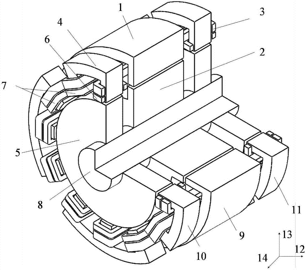
[0061] Such as figure 1 Shown is a three-dimensional structural schematic diagram of a four-degree-of-freedom composite structure bearingless switched reluctance motor of the present invention, wherein, 1 is a reluctance motor stator, 2 is a reluctance motor rotor, 3 is an armature winding, and 4 is a magnetic bearing stator. 5 is a magnetic bearing rotor, 6 is a suspension winding, 7 is a bias winding, 8 is a rotating shaft, 9 is a 12 / 8-pole switched reluctance motor, 10 is a radial magnetic bearing I, 11 is a radial magnetic bearing II, 12, 13 and 14 are the positive directions of the coordinate axes in the x, y and z directions respectively.

[0062] The four-degree-of-freedom composite structure bearingle...


PUM


Abstract

The invention discloses a four-degree-of-freedom composite structure bearingless switch reluctance machine and a controlling method thereof. The motor is composed of a switch reluctance machine and two radial magnetic bearings. Each magnetic bearing stator is formed by four E-type structures; one suspension winding and one armature winding wind around a middle tooth of each E-type structure; and one bias winding and one armature winding wind around two tooth windings. One armature winding winds around each tooth of the switch reluctance machine and crosses over the two magnetic bearing stators and a switch reluctance machine stator. An A-phase armature winding forms one phase; and B-phase and C-phase armature windings and bias windings are connected in series to form another two phases. A torque controlling way is identical with a traditional switch reluctance machine controlling way. The suspension force at a certain direction of each magnetic bearing is only related with a three-phase armature winding current and a suspension current at the direction; and the torque and the suspension force as well as the torque and the radial suspension force is in decoupling controlling. The suspension controlling becomes simple; and the outputs of the suspension forces are balanced and symmetric.

Description

technical field [0001] The invention relates to a four-degree-of-freedom composite structure bearingless switched reluctance motor and a control method thereof, belonging to the technical field of magnetic levitation switched reluctance motors and their control. Background technique [0002] Bearingless switched reluctance motors not only have the advantages of frictionless and non-lubricated magnetic bearings, but also inherit the high-speed adaptability of switched reluctance motors and meet harsh working environments. They are used in aerospace, flywheel energy storage, and military applications. Unique advantages. [0003] The four-degree-of-freedom composite structure bearingless switched reluctance motor is a new type of magnetic levitation motor. As the bias flux required to generate the levitation force; in addition, since the magnetic bearing and the switched reluctance motor are isolated from each other, the levitation operation has no effect on the electric rotat...

Claims


Application Information

Patent Timeline
Patent Type & Authority Applications(China)
IPC IPC(8): H02N15/00
CPCH02N15/00
Inventor 刘泽远蔡骏杨艳曹鑫邓智泉郭前岗
Owner NANJING UNIV OF POSTS & TELECOMM
Why Eureka
Try Eureka