Relay connection device for forced ventilation equipment, relay connection system including same, and forced ventilation equipment provided with such systems

A connection device, forced ventilation technology, applied in ventilation systems, heating and ventilation control systems, heating and ventilation safety systems, etc., can solve problems such as failure to reach relay fan flow and entry of dirty air

Inactive Publication Date: 2017-07-11
ETUD & CONSTR ELECTROMECANIQUES
View PDF8 Cites 0 Cited by
  • Summary
  • Abstract
  • Description
  • Claims
  • Application Information

AI Technical Summary

Problems solved by technology

The initial estimated air margin during pressurization is 10-20%, and it will be provided by the relay fan, so the margin will be reduced, even not reaching the flow rate of the relay fan
In addition, due to the problem of dirty air ent

Method used


Image

  • Relay connection device for forced ventilation equipment, relay connection system including same, and forced ventilation equipment provided with such systems
  • Relay connection device for forced ventilation equipment, relay connection system including same, and forced ventilation equipment provided with such systems
  • Relay connection device for forced ventilation equipment, relay connection system including same, and forced ventilation equipment provided with such systems

Examples


Embodiment Construction

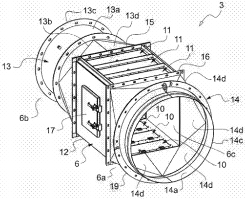
[0049] If first refer to image 3 , a schematic diagram of a part of a ventilation device 1 according to a specific embodiment of the present invention can be seen, specifically the area between the end of the first pipe section and the beginning of the next pipe section.

[0050] Compared with the conventional forced ventilation equipment with relay fans, the equipment 1 is different in that it is equipped with a relay connection system 2 , which includes a relay connection device 3 and an automatic device 4 . A transmission has also been designed that has been used in conventional equipment.

[0051] like will be combined Figures 5 to 8 As described in detail, the relay connection device 3 comprises a pipe system 6 having a first end 6a, which is hermetically connected to the end of the sleeve 7 forming the first pipe section, and a second end 6b , which is hermetically connected with a relay fan 8, more specifically its air inlet 8a.

[0052] Said relay fan 8 can be adj...


PUM


Abstract

The invention relates to a relay connection device (3) for forced ventilation equipment (1) having relay fan(s) (8), which includes a duct assembly (6) forming an inner channel (6c) of which the ends (6a, 6b) are open and provided with attachment means (13c, 14c) designed for a sealed connection between a so-called upstream line section (7) and a subsequent line section (7) provided with a relay fan (8), so as to establish fluid communication therebetween, the duct assembly (6) also being provided with means (9) for measuring at least one parameter of the flow with a view to controlling the operation of the relay fan (8) so as to obtain the desired flow conditions at the end of the upstream line section (7). The invention also describes a relay connection system (2) including said relay connection device (3) and forced ventilation equipment (1) including such relay connection systems (2).

Description

technical field [0001] The present invention relates to the field of duct ventilation, in particular to a relay connection device for forced ventilation equipment, a relay connection system including such a device, and a forced ventilation device equipped with at least one such system. Background technique [0002] In the discharge process, for duct ventilation, outside air is usually drawn and made to flow along the duct through a ventilation line until it reaches the working surface and a fan is provided at its end, through which the outside air is sucked. [0003] In the case of particularly long ducts and / or particularly small cross-sectional areas, it may be necessary to use one or more so-called relay fans, which are placed between two continuous pipe sections of the ventilation line, in this case Divided into a series of pipe sections, there is a certain space between the end of the pipe section and the corresponding relay fan, which allows free discharge from the end...

Claims


Application Information

Patent Timeline
IPC IPC(8): F24F7/06F24F11/00F24F13/02
CPCF24F11/62F24F11/77F24F11/30F24F7/06F24F13/02F24F11/64F24F2110/40F24F2110/00Y02B30/70
Inventor 克里斯·诺里斯
Owner ETUD & CONSTR ELECTROMECANIQUES
Why Eureka
Try Eureka