Switching system and method of visible light communication and power line communication
A technology of power line communication and visible light communication, which is applied in the field of visible light communication, can solve the problems that the system cannot communicate normally, and achieve the effect of strong adaptability to the environment and wide applicability
- Summary
- Abstract
- Description
- Claims
- Application Information
AI Technical Summary
Problems solved by technology
Method used
Image

Examples
Embodiment 1
[0059] Please refer to Figure 1 to Figure 2 , Embodiment 1 of the present invention is:
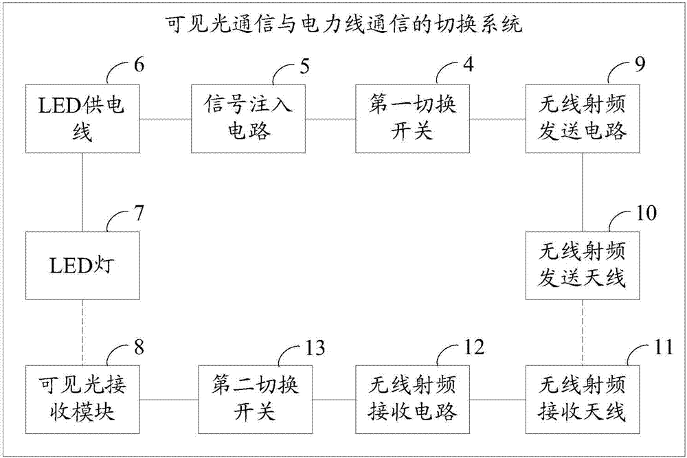
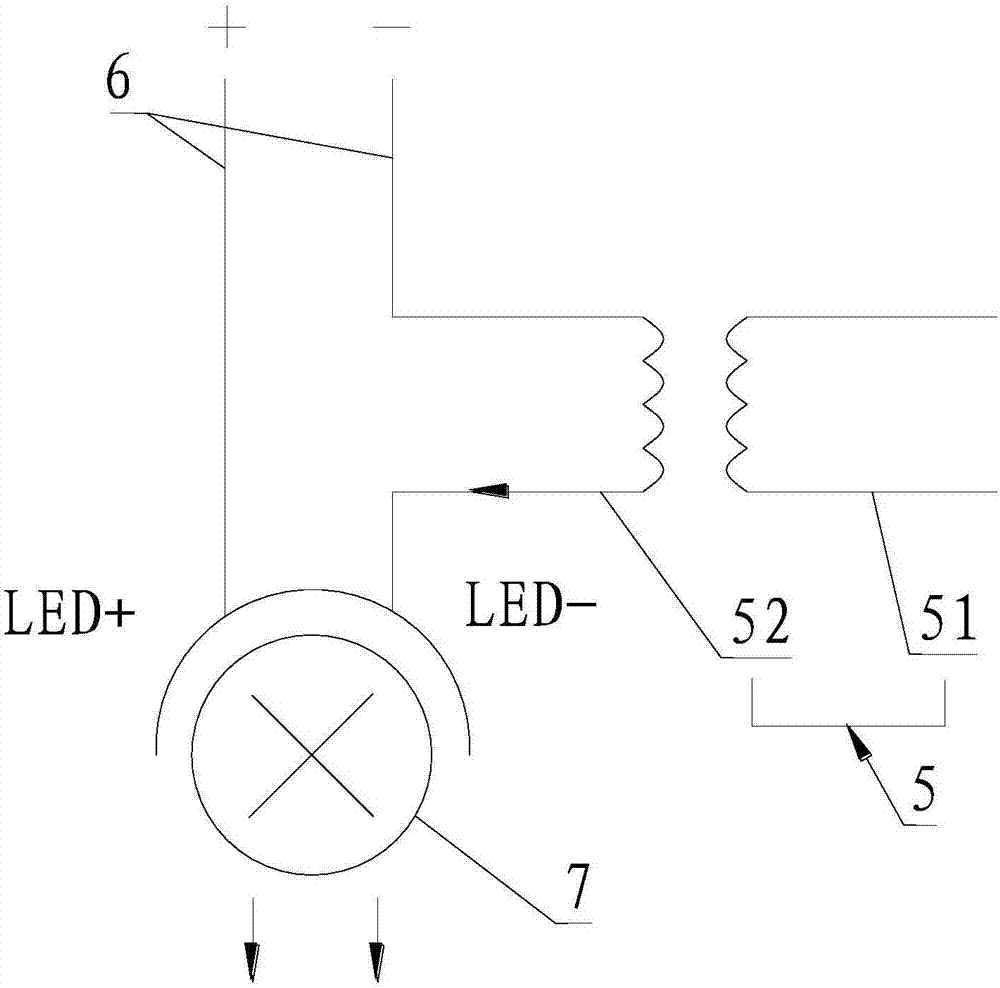
[0060] A switching system for visible light communication and power line communication, including a first switch 4, a signal injection circuit 5, an LED power supply line 6, an LED lamp 7, a visible light receiving module 8, a second switch 13, a wireless radio frequency transmission circuit 9, a wireless radio frequency transmitting antenna 10, radio frequency receiving antenna 11, radio frequency receiving circuit 12,
[0061] The first switch 4 is electrically connected to the signal injection circuit 5, the signal injection circuit 5 is connected to the LED power supply line 6, the LED power supply line 6 is electrically connected to the LED lamp 7, and the visible light The receiving module 8 is used to receive the light signal of the LED lamp 7, and the visible light receiving module 8 is electrically connected to the second switch 13;
[0062] The first switch 4 is also electric...
Embodiment 2
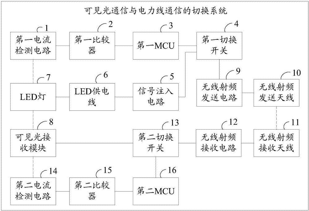
[0065] Please refer to image 3 , the second embodiment of the present invention is:
[0066] A switching system for visible light communication and power line communication, on the basis of Embodiment 1, further includes a first current detection circuit 1, a first comparator 2, a first MCU 3, a second current detection circuit 14, and a second comparator 15 , the second MCU16, the first current detection circuit 1 is used to detect the current of the LED lamp 7, the first current detection circuit 1 is electrically connected to the first comparator 2, and the first comparator 2 It is electrically connected to the first MCU3, and the first MCU3 is electrically connected to the first switch 4; the second current detection circuit 14 is used to detect the current of the visible light receiving module 8, and the second current The detection circuit 14 is electrically connected to the second comparator 15, the second comparator 15 is electrically connected to the second MCU16, a...
Embodiment 3
[0068] Please refer to Figure 4 , Embodiment three of the present invention is:
[0069]A switching system for visible light communication and power line communication, on the basis of the second embodiment, further includes a first carrier communication module 17 and a second carrier communication module 18, the first carrier communication module 17 and the first switch 4 are electrically connected, the second carrier communication module 18 is electrically connected to the second switch 13, the first carrier communication module 17 is connected to the external signal circuit 21, and the second carrier communication chip 20 is connected to the The above-mentioned user terminal equipment 22 is connected. The transmission medium of the external signal circuit 21 and the user terminal equipment 22 can be any one of power lines, coaxial cables, electromagnetic waves, air, and optical fibers.
[0070] The signal of the external signal circuit 21 reaches the first switch 4 after...
PUM
 Abstract
Description
Claims
Application Information
 - R&D
- Intellectual Property
- Life Sciences
- Materials
- Tech Scout
- Unparalleled Data Quality
- Higher Quality Content
- 60% Fewer Hallucinations
Browse by: Latest US Patents, China's latest patents, Technical Efficacy Thesaurus, Application Domain, Technology Topic, Popular Technical Reports.
© 2025 PatSnap. All rights reserved.Legal|Privacy policy|Modern Slavery Act Transparency Statement|Sitemap|About US| Contact US: help@patsnap.com