Stretcher trolley for postoperative patient transfer

The technology of a stretcher car and a transfer car is applied to transfer a stretcher car for postoperative patients. In the field of transport, it can solve the problems of time-consuming and laborious handling, bumps, and aggravating the patient's condition, so as to improve stability and comfort, facilitate locking and separation, and reduce labor intensity.

Inactive Publication Date: 2018-06-05
WENZHOU UNIVERSITY
View PDF12 Cites 0 Cited by
  • Summary
  • Abstract
  • Description
  • Claims
  • Application Information

AI Technical Summary

Problems solved by technology

[0002] Post-operative patients and critically ill patients need to be transferred between the operating table and the hospital bed after the operation or after the operation is completed. However, due to reasons such as anesthesia or trauma, patients are often unable to move or need to restrict their activities, which requires multiple doctors and nurses. Personnel carry patients at the same time, which not only requires a lot of manpower, but also takes time and effort, and it is difficult to maintain stability when carrying
At the same time, during the transportation process, due to the different strength of each carrier, it is easy to have uneven manpower during transportation, resulting in unexpected bumps and aggravating the patient's condition
Most of the stretchers in the market are folding stretchers, which rely on manual transfer of patients on the stretchers, and their length cannot be stretched or contracted. When carrying the wounded, there is a fixed position, and the movement of the wounded is relatively large, and the labor intensity of the medical staff is extremely high. It is also relatively large, and it is easy to cause secondary injury to the patient.
Therefore, the existing technology has the problems of time-consuming and labor-intensive handling, poor stability and easy to cause secondary injury to patients.

Method used


Image

  • Stretcher trolley for postoperative patient transfer
  • Stretcher trolley for postoperative patient transfer
  • Stretcher trolley for postoperative patient transfer

Examples


Embodiment Construction

[0028] The present invention will be further described below in conjunction with the accompanying drawings and examples, but not as a basis for limiting the present invention.

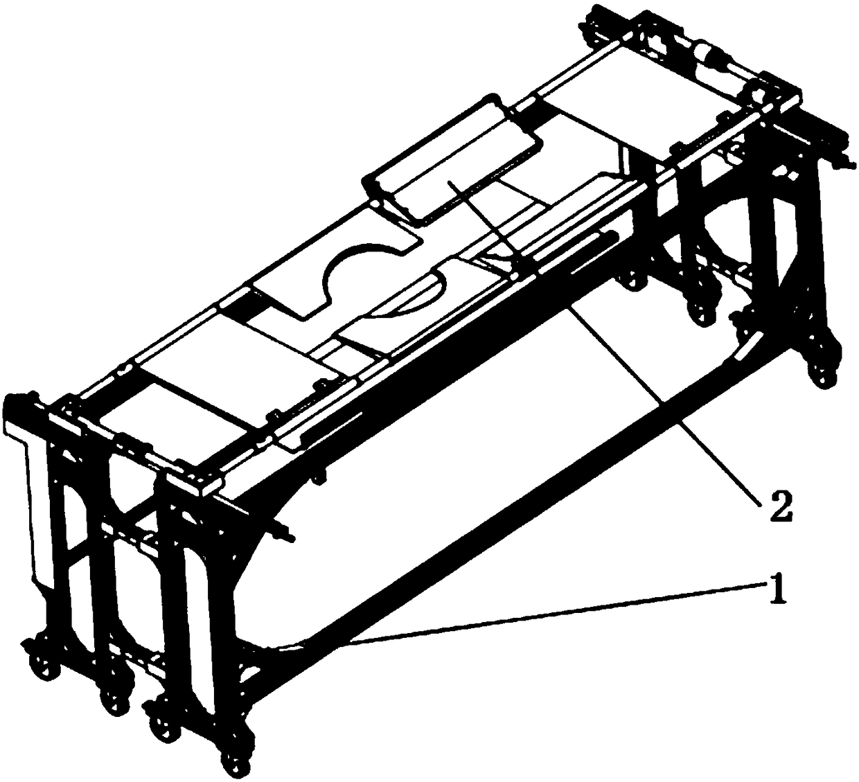
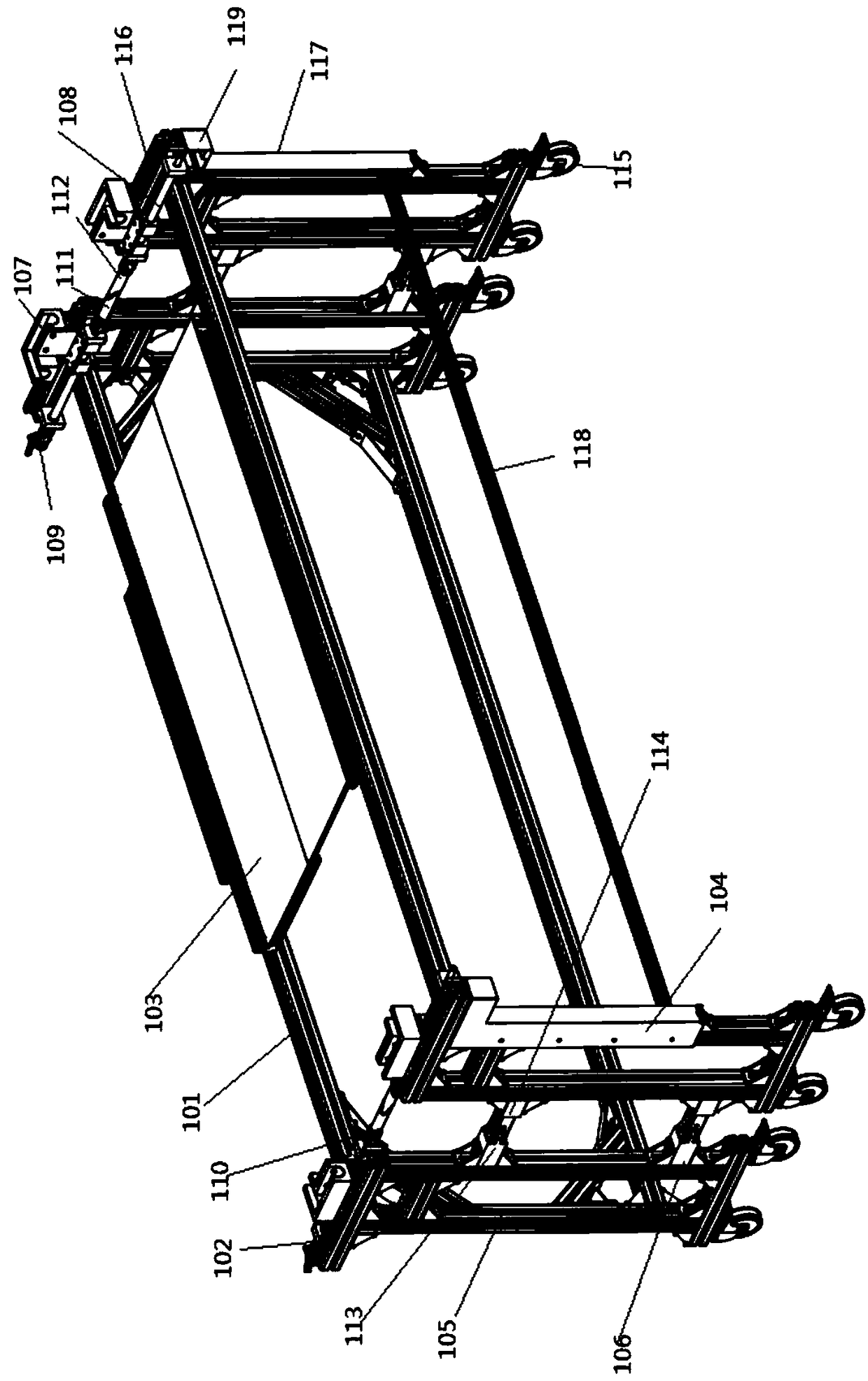
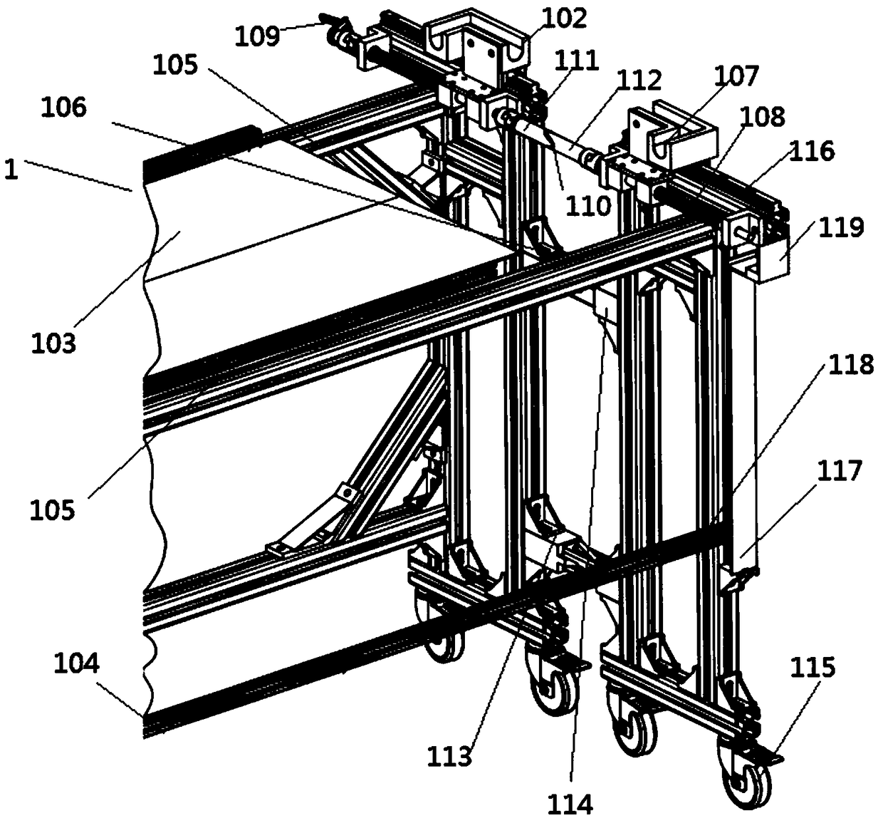
[0029] Example. A postoperative patient transfer stretcher cart, constituted as Figure 1 to Figure 12 As shown, it includes a transfer cart 1, and the transfer cart 1 is provided with a telescopic rotary stretcher 2; the transfer cart 1 includes a vehicle frame 101, and the upper end of the vehicle frame 101 is provided with a slideway locking unit 102 and a canvas folding unit 103, and the vehicle frame The lower end of the stretcher 101 is provided with a moving wheel 115, and the side of the vehicle frame 101 is provided with a movable rod moving unit 104; The clutch unit 202, the frame 201 is provided with a hip plate 203 and a push plate telescopic rotation unit 204, and the frame 201 is also provided with a frame telescopic unit 205.

[0030] The vehicle frame 101 includes two separate vehicle...


PUM


Abstract

The invention discloses a postoperative patient transfer stretcher cart, which comprises a transfer cart (1), on which a telescopic rotating stretcher (2) is arranged; the transfer cart (1) includes a frame (101), The upper end of the vehicle frame (101) is provided with a slideway locking unit (102) and a canvas folding unit (103), the lower end of the vehicle frame (101) is provided with moving wheels (115), and the side of the vehicle frame (101) is provided with a movable rod The mobile unit (104); the telescopic rotary stretcher (2) includes a frame (201) matched with the slideway locking unit (102), and a frame clutch unit (202) is provided at both ends of the frame (201), and the frame ( 201) is provided with a buttock plate (203) and a push plate telescopic rotation unit (204), and the frame (201) is also provided with a frame telescopic unit (205). The invention has the characteristics of improving the transport efficiency, reducing the labor intensity of medical personnel, improving the stability and reliability of transport and reducing the impact on patients.

Description

technical field [0001] The invention relates to a stretcher transfer device, in particular to a stretcher trolley for postoperative patient transfer. Background technique [0002] Post-operative patients and critically ill patients need to be transferred between the operating table and the hospital bed after the operation or the operation is completed, and the patients are often unable to move or need to restrict their activities due to reasons such as anesthesia or trauma, which requires multiple doctors and nurses Personnel carry patients at the same time, which not only requires a lot of manpower, is time-consuming and laborious to carry, but also is difficult to maintain stability when carrying. At the same time, in the process of carrying, due to the different strength of each carrying person, uneven manpower is prone to occur during carrying, resulting in unexpected bumps and aggravating the patient's condition. Most of the stretchers in the market are folding stretch...

Claims


Application Information

Patent Timeline
Patent Type & Authority Patents(China)
IPC IPC(8): A61G1/02A61G1/04
CPCA61G1/02A61G1/04A61G2203/70
Inventor 李振哲屠佳炜刘高爽沈碟陈怀枢叶淑祯
Owner WENZHOU UNIVERSITY
Why Eureka
Try Eureka