
Gyroscope correcting system and method based on astronomical azimuth

A calibration system and gyroscope technology are applied in the field of gyroscope calibration system based on astronomical azimuth angle, which can solve the problem that the calibration accuracy of the calibration method cannot meet the actual requirements, and achieve the effect of improving the accuracy

Active Publication Date: 2017-07-14
SHANGHAI INST OF MEASUREMENT & TESTING TECH
View PDF5 Cites 6 Cited by
  • Summary
  • Abstract
  • Description
  • Claims
  • Application Information

AI Technical Summary

Problems solved by technology

[0008] The invention provides a gyroscope calibration method based on astronomical azimuth, which solves the problem that the calibration accuracy of the existing calibration method cannot meet the actual requirements

Method used


Image

  • Gyroscope correcting system and method based on astronomical azimuth
  • Gyroscope correcting system and method based on astronomical azimuth
  • Gyroscope correcting system and method based on astronomical azimuth

Examples


Embodiment Construction

[0045] The specific implementation manner of the present invention will be described in detail below in conjunction with the accompanying drawings and preferred embodiments.

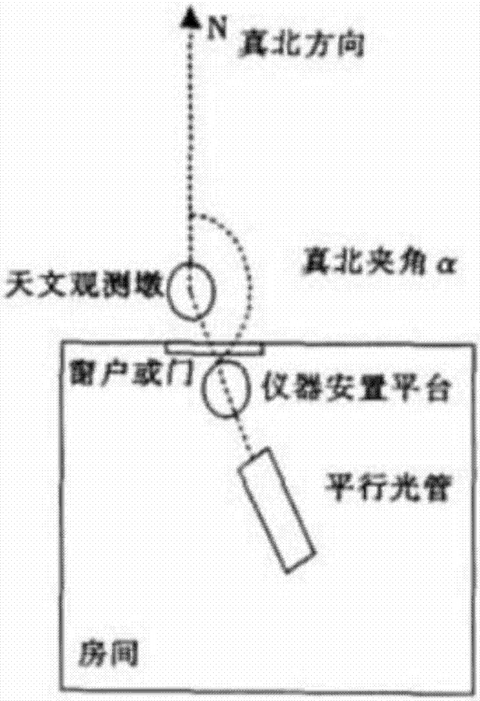
[0046] Such as figure 1 As shown, the present invention provides a kind of gyroscope calibration system based on astronomical azimuth, and this system comprises: astronomical observation pier, collimator and the gyroscope installation device that is positioned at the connecting line of astronomical observation pier and collimator, this gyroscope The gyroscope installation device is used to place the gyroscope to be calibrated, and can realize the adjustment of the gyroscope to be calibrated at any angle on the horizontal plane.

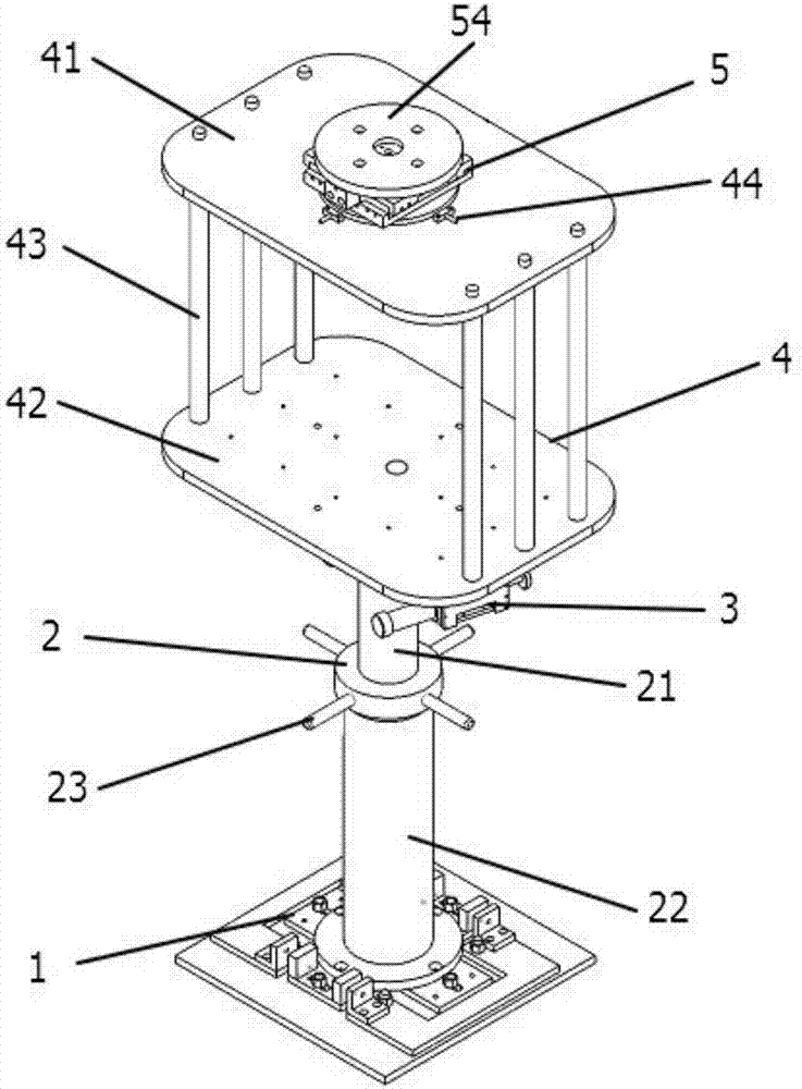
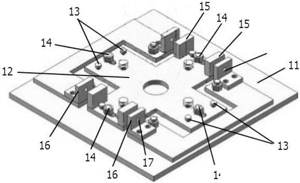
[0047] Such as figure 2 As shown, the gyroscope installation device includes a coaxially arranged adjustment and positioning mechanism 1, a spiral lifting platform 2, an angle adjustment mechanism 3, a gyroscope rotary platform 4 and a theodolite installation platform 5 from b...


PUM


Abstract

The invention relates to the technical field of gyroscope correction and discloses a gyroscope correcting system based on an astronomical azimuth. The gyroscope correcting system comprises an astronomical observation pillar, a parallel light tube and a gyroscope placement device, wherein the gyroscope placement device is located on a connecting line between the astronomical observation pillar and the parallel light tube and is used for placing a to-be-corrected gyroscope and adjusting the to-be-corrected gyroscope in any angle on a horizontal plane. The invention further discloses a gyroscope correcting method based on the astronomical azimuth. The gyroscope correcting method comprises the following steps of carrying out centering adjustment on an optical center of a theodolite or a down-hanging type gyro theodolite and a mark of a backlight grid plate; and making comparison on an azimuth measured by virtue of the to-be-corrected gyroscope or the down-hanging type gyro theodolite and an zero degree azimuth or an astronomical azimuth of the parallel light tube, so as to make judgment. According to the system and the method, the astronomical azimuth of the parallel light tube is combined with the centering adjustment, so that the correcting precision is improved.

Description

technical field [0001] The invention belongs to the technical field of gyroscope calibration, and in particular relates to a gyroscope calibration system and method based on astronomical azimuth. Background technique [0002] A gyroscope is an angular motion detection device that can accurately indicate the direction of true north under the combined action of gravity and rotation force on the earth. According to different principles of measurement and control, gyroscopes are divided into: piezoelectric gyroscopes, micromechanical gyroscopes, fiber optic gyroscopes, laser gyroscopes, etc. A gyroscope is a pointing instrument that does not depend on external signals and can work independently. Widely used in attitude and track control of moving objects, it is a key instrument for navigation and control of rockets, aircraft, ships and vehicles. As the gyroscope is limited by the manufacturing technology, its output azimuth angle has different degrees of indication deviation, ...

Claims


Application Information

Patent Timeline
IPC IPC(8): G01C25/00
CPCG01C25/005
Inventor 马建敏张伟张小嫚
Owner SHANGHAI INST OF MEASUREMENT & TESTING TECH
Learn More