Shoulder joint fixing frame
A fixed frame and shoulder joint technology, applied in shoulder bandages, medical science, orthopedic corsets, etc., can solve problems such as upper limb blood flow disorders, poor patient compliance, poor endurance, etc., to avoid complications, structure Simple, highly reliable effect
- Summary
- Abstract
- Description
- Claims
- Application Information
AI Technical Summary
Problems solved by technology
Method used
Image
Examples
Embodiment 1
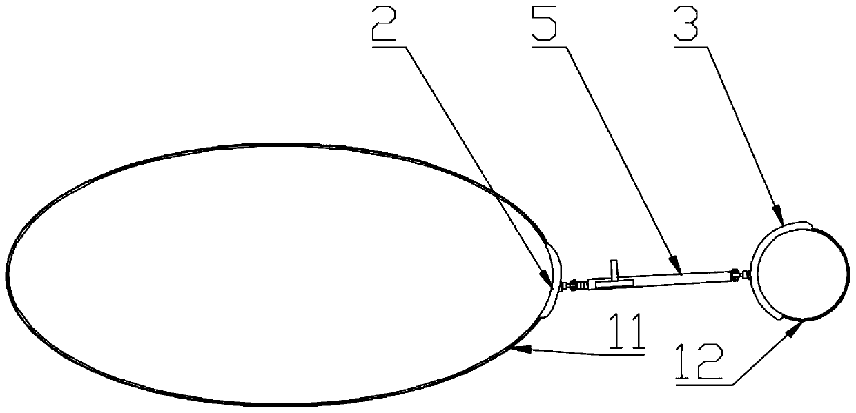
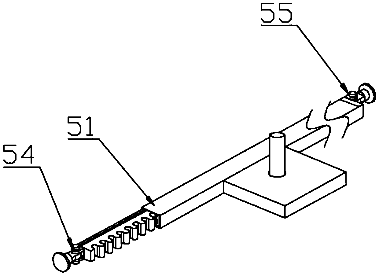
[0041] Such as figure 1 and figure 2 As shown, a shoulder joint fixation frame includes a chest wall fixing band 11, an upper arm fixing band 12, a first supporting plate 2, a second supporting plate 3 and a first fixing frame 5, and the first fixing frame 5 includes a telescopic member 51, a A rotating pair 54 and a second rotating pair 55, one end of the telescopic member 51 is connected with the first supporting plate 2 through the first rotating pair 54, the first supporting plate 2 is connected with the chest wall fixing belt 11, and the other end of the telescopic member 51 passes through the first supporting plate 2. The second rotating pair 55 is connected with the second supporting board 3 , and the second supporting board 3 is connected with the upper arm fixing belt 12 .
[0042]During use, the first supporting plate 2 is fixed on the chest wall of the human body with the chest wall fixing belt 11, and the second supporting plate 3 is fixed on the upper arm with t...
Embodiment 2
[0044] Such as Figure 4 As shown, on the basis of Embodiment 1, the telescopic member 51 includes a rack body 511, a rack housing 512, a manual gear 513, a gear shaft 514 for driving the manual gear 513 to rotate, and a gear housing 515, and the rack housing 512 is in the shape of a cuboid One end of the rack body 511 is connected to the first rotary pair 54, the other end of the rack body 511 is located in the rack housing 512, the middle part of the rack housing 512 is connected to the gear housing 515, the manual gear 513 is located in the gear housing 515 and Engaged with the rack body 511 , a central hole is provided on the gear housing 515 , and the gear shaft 514 is connected with the manual gear 513 through the central hole.
[0045] With the rack body 511 and the manual gear 513 as the mode of adjusting the telescopic member 51, the structure is simple, the reliability is high, and it can be adjusted to any length within a certain range.
Embodiment 3
[0047] On the basis of Embodiment 2, the rack body 511 is connected to the internal slide rail of the rack housing 515, the rack body 511 is provided with a groove along the length direction of the rack body 511, and the inner side of the rack housing 512 is provided with Elongated protrusions that fit into grooves.
[0048] The rack body 511 and the rack housing 512 slide relative to each other along the groove, which can enhance the stability of the telescopic member 51 and prevent shaking during use.
PUM
 Abstract
Description
Claims
Application Information
 - R&D
- Intellectual Property
- Life Sciences
- Materials
- Tech Scout
- Unparalleled Data Quality
- Higher Quality Content
- 60% Fewer Hallucinations
Browse by: Latest US Patents, China's latest patents, Technical Efficacy Thesaurus, Application Domain, Technology Topic, Popular Technical Reports.
© 2025 PatSnap. All rights reserved.Legal|Privacy policy|Modern Slavery Act Transparency Statement|Sitemap|About US| Contact US: help@patsnap.com


