Joint test management method and apparatus

A management method and joint debugging technology, applied in the computer field, can solve the problems of low management efficiency of joint testing and testing, and achieve the effects of improving joint testing items, improving management efficiency, and improving efficiency

Active Publication Date: 2017-07-14
MICRO DREAM TECHTRONIC NETWORK TECH CHINACO
View PDF12 Cites 12 Cited by
  • Summary
  • Abstract
  • Description
  • Claims
  • Application Information

AI Technical Summary

Problems solved by technology

[0005] The embodiment of the present application provides a management method of joint debugging test to solve the problem of low management efficiency of joint debugging test in the prior art
[00

Method used


Image

  • Joint test management method and apparatus
  • Joint test management method and apparatus
  • Joint test management method and apparatus

Examples


Embodiment 1

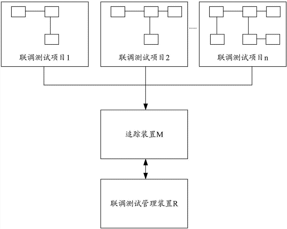
[0027] like figure 2 As shown, it is a schematic diagram of the steps of the management method for the joint debugging test involved in the embodiment of the present invention, wherein the method is mainly applied to the above-mentioned figure 1 In the application scenario of , the tracking device involved in the solution of the present invention is mainly described by taking JIRA as an example, and in fact, it can also be an RT system; the method mainly includes the following operations:

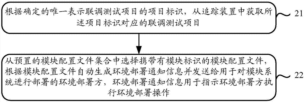
[0028] Step 21: According to the determined item identifier that uniquely represents the joint debugging test item, obtain the joint debugging test item corresponding to the item identifier from the tracking device, wherein the joint debugging test item at least includes: the project identifier and the module system. The module identifier of the module can reflect the required environment of the module.

[0029] In fact, for any item that JIRA can track and handle, it is necessary to add ...

Embodiment 2

[0059] It belongs to the same inventive concept as the above-mentioned management method for joint debugging and testing, and an embodiment of the present invention further provides a management device for joint debugging and testing.

[0060] refer to Figure 5 As shown, it is a schematic structural diagram of a joint debugging test management device provided by an embodiment of the present invention, and the device mainly includes the following functional units:

[0061]The first obtaining unit 51 is used to obtain the joint debugging test item corresponding to the item identification from the tracking device according to the determined project identifier that uniquely represents the joint debugging test item, wherein the joint debugging test item at least includes: Identification and identification of modules in the module system;

[0062] The generating unit 52 is configured to select a module configuration file carrying the module identifier from the preset module config...


PUM


Abstract

The invention relates to the technical field of computers, in particular to a joint test management method and apparatus, which is used for solving the problem of low management efficiency of a joint test in the prior art. According to the scheme, the method comprises the steps of obtaining a joint test project from a tracking apparatus by utilizing a determined project identifier and performing storage; and then, selecting a matched module configuration file from a preset module configuration file set according to a module identifier contained in the obtained joint test project, thereby generating environment deployment notification information used for indicating a deployment party to perform environment deployment operation. Working personnel do not need to subjectively identify and manually add environment deployment contents, and corresponding environment deployment contents are automatically selected, matched and generated according to the preset module configuration file, so that errors possibly caused by artificial participation are reduced; and meanwhile, the environment deployment contents are automatically generated, so that the environment deployment time is relatively shortened, the environment deployment efficiency of the joint test is improved, and the management efficiency of the joint test project is improved.

Description

technical field [0001] The present application relates to the field of computer technology, and in particular, to a management method and device for joint debugging and testing. Background technique [0002] Joint debugging test, also known as assembly test or joint test, is to verify the correctness of the interface between modules, whether the data flow and control flow between each module realize its functions according to the design, and the correctness of the overall function after integration. In fact, joint debugging test is commonly understood as: the application system realizes business interaction with other systems through the interface platform, and needs to perform collaborative testing between systems before going online. [0003] At present, the project and thing tracking tool is mainly used to track and manage the joint debugging and testing, so as to realize the real-time monitoring of the joint debugging and testing process, and facilitate the staff to know...

Claims


Application Information

Patent Timeline
IPC IPC(8): G06F11/36G06Q10/10
CPCG06F11/3664G06F11/3688G06Q10/103
Inventor 曾雪梁田
Owner MICRO DREAM TECHTRONIC NETWORK TECH CHINACO
Why Eureka
Try Eureka