
Miniaturized antenna based on capacitive loading

A capacitive loading and antenna technology, which is applied to the antenna grounding device, the structural connection of the antenna grounding switch, the structural form of the radiating element, etc. The effect of miniaturization and simple design

Inactive Publication Date: 2017-07-14
WUHAN UNIV
View PDF2 Cites 3 Cited by
  • Summary
  • Abstract
  • Description
  • Claims
  • Application Information

AI Technical Summary

Problems solved by technology

[0003] Generally speaking, the miniaturization of the antenna is difficult to achieve, because it will reduce the bandwidth and efficiency of the antenna
Although the method of changing the shape of the antenna and adding a matching network can improve the performance of the antenna and reduce the size of the antenna to a certain extent, it will sacrifice most of the other performances including bandwidth, so the bandwidth of the miniaturized antenna can be widened by loading technology Become a prerequisite for the practical application of miniaturized antennas
[0004] At present, the miniaturization of antennas mainly adopts the method of inductive loading, and there are not many studies on capacitive loading.

Method used


Image

  • Miniaturized antenna based on capacitive loading
  • Miniaturized antenna based on capacitive loading

Examples


Embodiment Construction

[0021] Embodiments of the present invention will be described in detail below in conjunction with the accompanying drawings.

[0022] Examples of the described embodiments are shown in the drawings, wherein like or similar reference numerals designate like or similar elements or elements having the same or similar functions throughout. The embodiments described below by referring to the figures are exemplary only for explaining the present invention and should not be construed as limiting the present invention.

[0023] The following disclosure provides many different embodiments or examples for implementing different structures of the present invention. To simplify the disclosure of the present invention, components and arrangements of specific examples are described below. They are examples only and are not intended to limit the invention. Furthermore, the present invention may repeat reference numerals and / or letters in different instances. This repetition is for the pur...


PUM

PropertyMeasurementUnit
Thicknessaaaaaaaaaa
Radiusaaaaaaaaaa
Resonant frequencyaaaaaaaaaa

Abstract

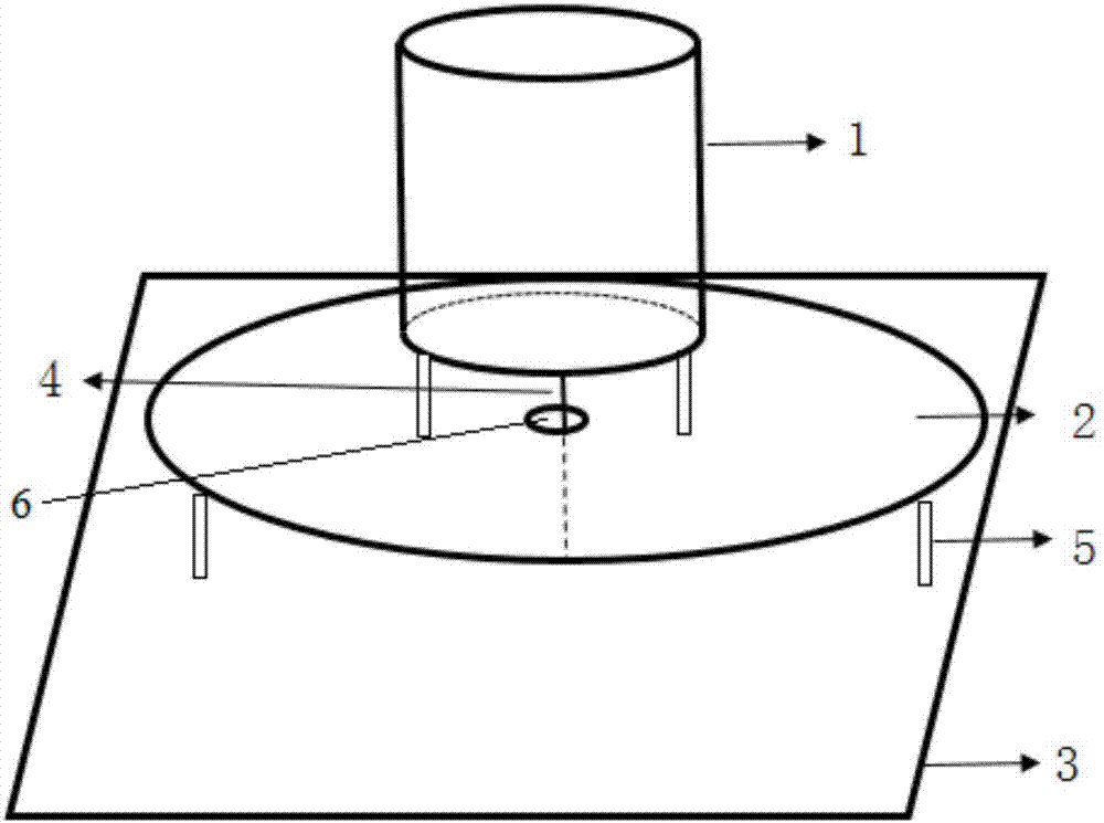
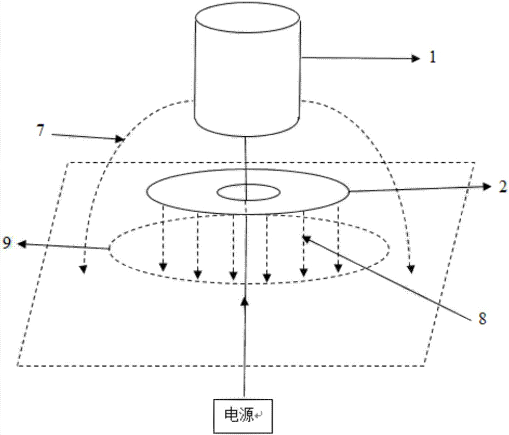
The invention relates to an antenna miniaturizing technology, in particular to a miniaturized antenna based on capacitive loading. The miniaturized antenna comprises a feed coaxial line, a metal drum, a grounding plate and a metal disk, wherein the metal drum and the grounding plate are arranged in parallel; the metal drum is positioned on the grounding plate; the metal disk is arranged between the metal drum and the grounding plate in parallel; the feed coaxial line passes through the metal disk, and is connected between the metal drum and the grounding plate respectively; and insulated bracket supports are arranged between the metal drum and the metal disk as well as between the metal disk and the grounding plate respectively. Through adoption of the miniaturized antenna, the inconvenience in use caused by overlarge size of an antenna is avoided; miniaturization of the antenna is realized effectively under the condition of not reducing the working bandwidth; and meanwhile, the design is simple and convenient. The antenna is an omnidirectional antenna, has maximum radiation in a horizontal direction, and can keep high efficiency of 70 to 86 percent in a working frequency band. The antenna is 40cm in full height which is about a half of the size of a conventional antenna, and the aim of miniaturizing the antenna is fulfilled.

Description

technical field [0001] The invention belongs to the technical field of antenna miniaturization, in particular to a miniaturized antenna based on capacitive loading. Background technique [0002] Antennas are components that couple to radio waves in free space. Theoretically speaking, the size of the antenna is positively correlated with the wavelength of the radio wave to be sent and received, while the wavelength of the radio wave is inversely proportional to its frequency. That is to say, when the frequency of radio waves to be transmitted is very small, the corresponding wavelength is very long, and the required transceiver antenna is very large, and the size of the antenna is too large, which will inevitably cause inconvenience to its use. Therefore, it is necessary to study the miniaturization of the antenna, so that the antenna can normally radiate electromagnetic waves of the required wavelength, and on the other hand, the size should be reduced as much as possible t...

Claims


Application Information

Patent Timeline
IPC IPC(8): H01Q1/36H01Q1/50H01Q1/48
CPCH01Q1/36H01Q1/48H01Q1/50
Inventor 周庆陈章友
Owner WUHAN UNIV
Learn More