
A new type of new energy electric vehicle DC charging pile

A technology for DC charging piles and electric vehicles, which is applied in the direction of electric vehicle charging technology, electric vehicles, charging stations, etc. It can solve problems such as non-conformity with energy conservation and environmental protection, damage to charging lines, and increased difficulty, so as to improve operational efficiency and accuracy , Simple structure, reducing the effect of infrastructure construction

Active Publication Date: 2018-09-21
深圳市众通新能源汽车科技有限公司
View PDF7 Cites 0 Cited by
  • Summary
  • Abstract
  • Description
  • Claims
  • Application Information

AI Technical Summary

Problems solved by technology

The existing electric vehicle charging piles at home and abroad have a structure of one pile and one gun. In the same electric vehicle parking area, repeated infrastructure construction is required, resulting in increased construction difficulty, repeated investment, waste of resources, and inconformity with energy conservation and environmental protection.
In some cases where the construction environment does not allow, such as site limitations, one pile with multiple guns is more suitable; in addition, after the existing charging pile is charged, it is necessary to artificially put the charging line back into the charging pile, but the charging line Generally has a certain length, which brings great inconvenience to the user
In addition, the charging cable is exposed outside the charging pile. When the charging pile is not in use, the charging cable is placed on the side of the charging pile. When the charging cable is scattered in an improper position, there is a risk of the charging cable being crushed and collided by the electric vehicle and being damaged or getting an electric shock. risk

Method used


Image

  • A new type of new energy electric vehicle DC charging pile
  • A new type of new energy electric vehicle DC charging pile
  • A new type of new energy electric vehicle DC charging pile

Examples


Embodiment Construction

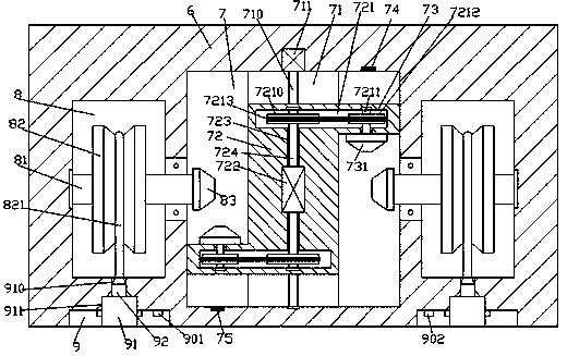
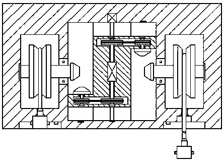
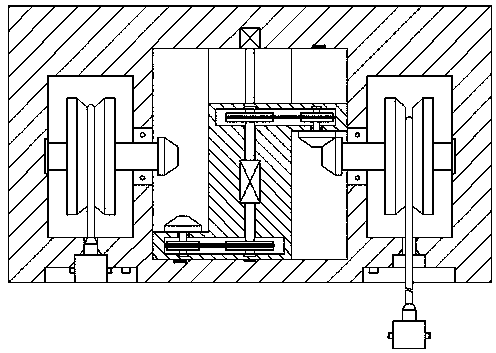
[0025] Such as Figure 1-Figure 7 As shown, a new type of new energy electric vehicle DC charging pile of the present invention includes a pile body 6, a control cavity 7 is provided in the middle of the pile body 6, and a wire take-up cavity is symmetrically arranged on the left and right sides of the control cavity 7 8. An operating groove 9 is provided in the outer wall of the pile body 6 on the front side of the wire receiving chamber 8, and a sliding groove 71 extending forward and backward is provided on the inner bottom wall of the operating chamber 7, and the sliding groove 71 is provided with A screw 710 extending forward and backward, the rear end of the screw 710 is power-connected with the first motor 711, and the sliding groove 71 is provided with a moving block 72 extending upward and extending into the control cavity 7, the moving block 72. A convex slider 73 is provided at the edge of the left front side and the right rear side. A transmission chamber 721 is pr...


PUM


Abstract

The invention discloses a novel direct current charging pile for a new energy electric vehicle. The novel direct current charging pile for the new energy electric vehicle comprises a pile body, a control cavity is arranged on the middle position of the interior of the pile body, a take-up cavity is symmetrically arranged on the left side and the right side of the control cavity, and an operation groove is formed in the outer wall of the pile body on the front of the take-up cavity; a sliding groove extending in the front-rear direction is formed in the bottom wall of the interior of the control cavity, a screw rod extending in the front-rear direction is arranged in the sliding groove, and the rear end of the screw rod is connected with a first motor in a dynamic mode; a movable block extending upwards and stretching into the control cavity is arranged in the sliding groove, convex sliding blocks are arranged on the edges of the left front side and the right rear side of the movable block correspondingly, and a transmission cavity is arranged between each convex sliding block and the movable block; and a second motor is arranged on the middle position of the movable block, through holes are formed in the front side and the rear side of the second motor correspondingly, and the outside ends of the through holes in the front side and the rear side communicate with the transmission cavities in the front side and the rear side of the movable block correspondingly. The novel direct current charging pile for the new energy electric vehicle is simple in structure, intelligent in prompt and control, simple in operation, and energy-saving and environmentally friendly, and can complete automatic take-up work, and prevent damages to charging line and electric shock accidents.

Description

technical field [0001] The invention relates to the technical field of new energy electric vehicle charging, in particular to a novel new energy electric vehicle DC charging pile. Background technique [0002] With the gradual depletion of oil resources, electric vehicles have been well developed in recent years. An electric vehicle refers to a vehicle powered by an on-board power supply and driven by a motor to drive the wheels. Compared with gasoline vehicles, it is more energy-saving and environmentally friendly, so it is being promoted by countries all over the world. The existing electric vehicle charging piles at home and abroad have a structure of one pile and one gun. In the same electric vehicle parking area, repeated infrastructure construction is required, resulting in increased construction difficulty, repeated investment, waste of resources, and non-conformity to energy conservation and environmental protection. In some cases where the construction environment...

Claims


Application Information

Patent Timeline
Patent Type & Authority Patents(China)
IPC IPC(8): B60L11/18B65H75/38
CPCB60L53/31B65H75/38Y02T10/70Y02T10/7072Y02T90/12
Inventor 梁敏华
Owner 深圳市众通新能源汽车科技有限公司
Learn More