Automatic draining tank

A drainage box and automatic technology, applied in steam/steam condensers, lighting and heating equipment, etc., can solve the problems of complex construction, many consumables, and sundries falling into it, so as to reduce construction difficulty and engineering quantity, and ensure safe operation The effect of reliable, wide applicability

Inactive Publication Date: 2017-07-18
CEEC JIANGSU ELECTRIC POWER DESIGN INST
View PDF1 Cites 2 Cited by
  • Summary
  • Abstract
  • Description
  • Claims
  • Application Information

AI Technical Summary

Problems solved by technology

[0004] Single-stage water seals and multi-stage water seals generally have some problems in the operation of power plants. Due to the insufficient height of the water seal or the vaporization of the medium, the single-stage water seal is easy to cause the water seal to be evacuated, and the front-end steam directly rushes into the condenser, affecting The vacuum degree of the main engine; the multi-stage water seal is composed of several single-stage water seals connected in series. Due to the influence of impurities or calculation height, it is easy to cause poor drainage
[0005] The structure of single-stage and multi-stage water seals is large in size, requires more materials during construction, is complex in construction, and takes up a large space. If buried underground, it is easily affected by the surrounding foundation construction, causing the water seal pipe to bend and deform. At the same time It is also easy for debris to fall into it. After the impurities enter the water-sealed pipe, they will accumulate in the U-shaped pipe, which is difficult to check and remove. normal operation

Method used


Image

  • Automatic draining tank

Examples


Embodiment Construction

[0020] The present invention will be specifically introduced below in conjunction with the accompanying drawings and specific embodiments.

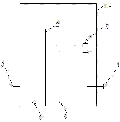
[0021] Taking a 300MW class unit as an example, the automatic drainage box is a rectangular box body 1 with dimensions of 600×600×800mm in length, width and height. The automatic drainage box can be arranged on the ground or at the bottom of the pipe pit. The box body 1 is divided into a water inlet area and a water outlet area by a partition 2. The water level control automatic float 5 valve is installed in the water outlet area to control the sealing of the water outlet 4. The water outlet 4 is connected to the condenser.

[0022] when working,

[0023] The normal working pressure is atmospheric pressure, and when just starting to work, there is no water level in the water inlet area and the water outlet area, and now the float 5 valve in the water outlet area falls, and the cap seals the water outlet 4.

[0024] When the unit is put ...


PUM


Abstract

The invention discloses an automatic draining tank. An inner cavity of a tank body is divided into a water inlet area and a water outlet area through a partition plate. The water inlet area is provided with a water inlet, the water outlet area is provided with a water outlet with a sealing cover, and the sealing cover is connected with a floating ball. A draining tank type is used for replacing single-level water seal pipes and multi-level water seal pipes which are commonly used in a power plant at present. The partition plate is adopted in the draining tank for partitioning, the automatic floating ball is adopted for controlling the water level, and the water outlet is automatically closed; and the automatic draining tank is small in size, the construction difficulty and the project amount of water seal embedded pipes are greatly reduced, meanwhile, the phenomenon that a water seal is evacuated or draining is not smooth can be avoided, running safety of a draining system is improved, in addition, no special requirement for arrangement exists, more favorable conditions are provided for optimal arrangement of the area, and the problems that a traditional U-shaped water seal pipe is difficult to construct, poor in water seal effect and hard to repair and maintain are solved. The automatic draining tank is simple in structure, compact in arrangement, easy to built and maintain, small in occupied size, convenient to construct and safe and reliable in running and has very high practicability and wide applicability.

Description

technical field [0001] The invention relates to a drainage box, in particular to an automatic drainage box. Background technique [0002] The shaft seal heater in a thermal power plant is a shell-and-tube heat exchanger. The shell side receives steam leakage from the shaft seal system of the turbine, and is cooled and condensed by the tube side, and the water is recycled to the condenser. The condenser is in vacuum during normal operation. In order to prevent the drain from being evacuated and affect the vacuum of the condenser, U-shaped water-sealed tubes are generally used to seal the steam and air communication channels at the height of the water column. [0003] At present, the commonly used water seal tube types in power plants include single-stage water seal and multi-stage water seal. [0004] Single-stage water seals and multi-stage water seals generally have some problems in the operation of power plants. Due to the insufficient height of the water seal or the vapo...

Claims


Application Information

Patent Timeline
Patent Type & Authority Applications(China)
IPC IPC(8): F28B9/04
CPCF28B9/04
Inventor 徐蕾
Owner CEEC JIANGSU ELECTRIC POWER DESIGN INST
Why Eureka
Try Eureka