
Three dimensional morphology measuring instrument control method and system

A technology of three-dimensional shape and control method, which is applied in the field of measuring instrument control to achieve good technical effects

Active Publication Date: 2017-07-18
安徽金盾三维高科技有限公司
View PDF14 Cites 4 Cited by
  • Summary
  • Abstract
  • Description
  • Claims
  • Application Information

AI Technical Summary

Problems solved by technology

[0006] In view of the deficiencies in the prior art above, the purpose of the present invention is to provide a target attitude control algorithm for a three-dimensional shape measuring instrument and its software implementation, aiming to solve the problem that the three-dimensional shape measuring instrument is not fast and accurate in the prior art. The Problem of Controlling Measuring Target Attitude

Method used


Image

  • Three dimensional morphology measuring instrument control method and system
  • Three dimensional morphology measuring instrument control method and system
  • Three dimensional morphology measuring instrument control method and system

Examples


Embodiment Construction

[0057] The invention provides a control method and system for a three-dimensional shape measuring instrument. In order to make the object, technical solution and effect of the present invention more clear and definite, the present invention will be further described in detail below with reference to the accompanying drawings and examples. It should be understood that the specific embodiments described here are only used to explain the present invention, not to limit the present invention.

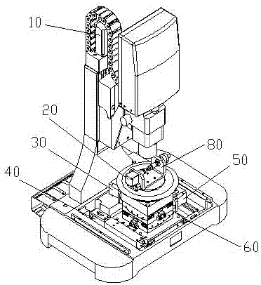
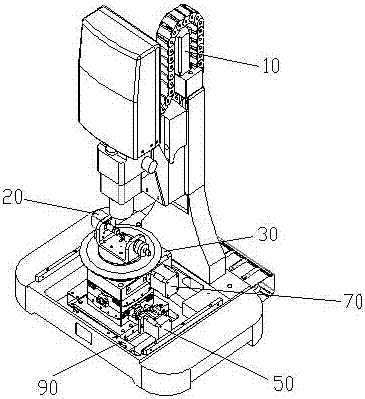
[0058] figure 1 and figure 2 A three-dimensional shape measuring instrument provided by an embodiment of the present invention. Such as figure 1 and figure 2 As shown, the three-dimensional shape measuring instrument includes: a Z-axis vertical movement motor 10, a measured object rotation motor 20, an X-axis rotation motor 30, a Y-axis translation motor 40, a Y-axis rotation motor 50, an X-axis rotation motor 60, and a Z-axis rotation motor. Axis rotation motor 70, Z-axis translatio...


PUM


Abstract

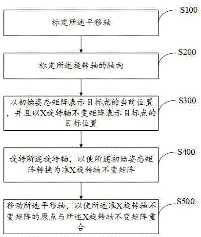
The invention provides a three dimensional morphology measuring instrument control method and system; the method comprises the following steps: calibrating a translation shaft; calibrating a turning axle axial direction, using an initial attitude matrix to express a target point present position, and using an X turning axle constant matrix to express the target point target position; rotating the turning axle, thus converting the initial attitude matrix into a quasi X turning axle constant matrix, wherein the reference axis directions of the quasi X turning axle constant matrix and the X turning axle constant matrix are same; translating the translation shaft, thus allowing the quasi X turning axle constant matrix origin to overlap with the X turning axle constant matrix.

Description

technical field [0001] The invention relates to the technical field of measuring instrument control, in particular to a control method and system for a three-dimensional shape measuring instrument. Background technique [0002] At present, the comparison and detection of forensic evidence, such as bullet bullets, shell casings, and traces of tool lines, is still in the state of storing and analyzing physical samples, and the detection of trace information still stays in the direct observation of two-dimensional with a single instrument. At the technical level of image comparison, it is impossible to solve the problem of precise positioning and measurement in three-dimensional space object shape technology and trace comparison technology. [0003] In recent years, with the maturity and development of the non-contact detection technology that was originally mainly used for the reconstruction of the three-dimensional shape of the object surface in engineering, there has been ...

Claims


Application Information

Patent Timeline
Patent Type & Authority Applications(China)
IPC IPC(8): G05D3/12
CPCG05D3/12
Inventor 刘贵兵
Owner 安徽金盾三维高科技有限公司
Learn More