Inflatable bed
An inflatable bed and air chamber technology, applied in the field of inflatable beds, can solve the problems of deformation air bed and air mattress stability, easy rollover, easy side wall expansion, etc., achieve beautiful appearance, prevent rolling, overcome easy sideways flip effect
- Summary
- Abstract
- Description
- Claims
- Application Information
AI Technical Summary
Problems solved by technology
Method used
Image
Examples
Embodiment 1
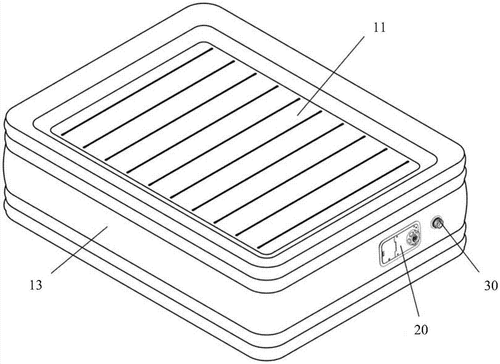
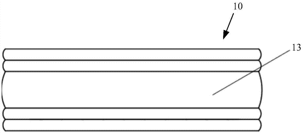
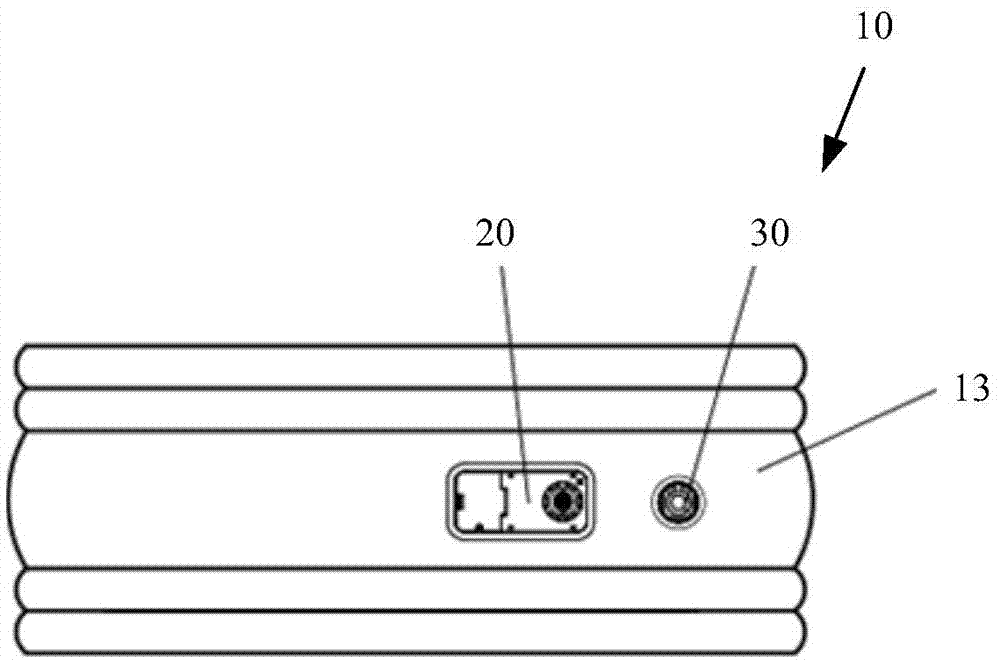
[0082] figure 1 It is a perspective view of the air bed of the present invention. figure 2 It is the front view of the air bed of the present invention. image 3 It is the right side view of the air bed of the present invention. Figure 4 It is a top view of the air bed of the present invention. Figure 5 for Figure 4 A cross-sectional view of Embodiment 1 cut along the A-A line. Figure 6 It is a schematic diagram of the local anatomical structure of Embodiment 1 of the air bed of the present invention. Figure 7 It is an exploded view of Embodiment 1 of the air bed of the present invention.
[0083] Such as Figure 1 to Figure 7 As shown, Embodiment 1 of the present invention discloses an air bed 10 , which includes a top sheet 11 , a bottom sheet 12 , at least one side wall 13 , at least one first drawstring structure 14 and at least one support structure. Wherein, bottom sheet 12 and top sheet 11 are spaced apart up and down, and the upper edge of side wall 13 is ...
Embodiment 2
[0099] Figure 9 for Figure 4 The sectional view of the second embodiment cut along the A-A line. Figure 10 Be the explosion of the embodiment two of air bed of the present invention Figure 1 . Figure 11 Be the explosion of the embodiment two of air bed of the present invention Figure II .
[0100] Such as Figure 9 to Figure 11 As shown, the structure of this embodiment is basically the same as that of Embodiment 1, except that the second drawstring structure 15 includes at least one first Y-shaped drawstring 151, wherein the two outer sides of the first Y-shaped drawstring 151 The edges 152 are respectively connected to the adjacent side walls 13 , and the other inner edge 153 is connected to the top sheet 11 . Similarly, the third drawstring structure 16 includes at least one second Y-shaped drawstring 161, wherein the two outer edges 162 of the second Y-shaped drawstring 161 are respectively connected to the adjacent side walls 13, and the other inner edge 163 i...
Embodiment 3
[0106] Figure 12 for Figure 4 The sectional view of the third embodiment cut along the A-A line Figure 1 . Figure 13 for Figure 4 The sectional view of the third embodiment cut along the A-A line Figure II . Figure 14 Be the explosion of the embodiment three of air bed of the present invention Figure 1 . Figure 15 Be the explosion of the embodiment three of air bed of the present invention Figure II .
[0107] Such as Figure 12 to Figure 15 As shown, the structure of this embodiment is basically the same as that of Embodiment 1, except that the second drawstring structure 15 includes at least one first tubular drawstring 151, wherein the first tubular drawstring 151 has at least two Two outer edges 152 are respectively connected with the adjacent sidewalls 13, and at least one other inner edge 153 is connected with the top sheet 11. The third drawstring structure 16 includes at least one second tubular drawstring 161, and the second tubular drawstring 161 ...
PUM
 Abstract
Description
Claims
Application Information
 - R&D
- Intellectual Property
- Life Sciences
- Materials
- Tech Scout
- Unparalleled Data Quality
- Higher Quality Content
- 60% Fewer Hallucinations
Browse by: Latest US Patents, China's latest patents, Technical Efficacy Thesaurus, Application Domain, Technology Topic, Popular Technical Reports.
© 2025 PatSnap. All rights reserved.Legal|Privacy policy|Modern Slavery Act Transparency Statement|Sitemap|About US| Contact US: help@patsnap.com


