
Pull buckle type suture device

A suturer and buckle-type technology, applied in the direction of wound clips, etc., can solve the problems of reducing the clamping force of ratchets and pawls, reducing the tension of the two substrates, and reducing the suture effect, so as to improve the locking tension and improve the elasticity. Deformation range, the effect of improving the stitching effect

Pending Publication Date: 2017-07-21
DONGGUAN MING LEI ELECTRONICS TECH
View PDF8 Cites 7 Cited by
  • Summary
  • Abstract
  • Description
  • Claims
  • Application Information

AI Technical Summary

Problems solved by technology

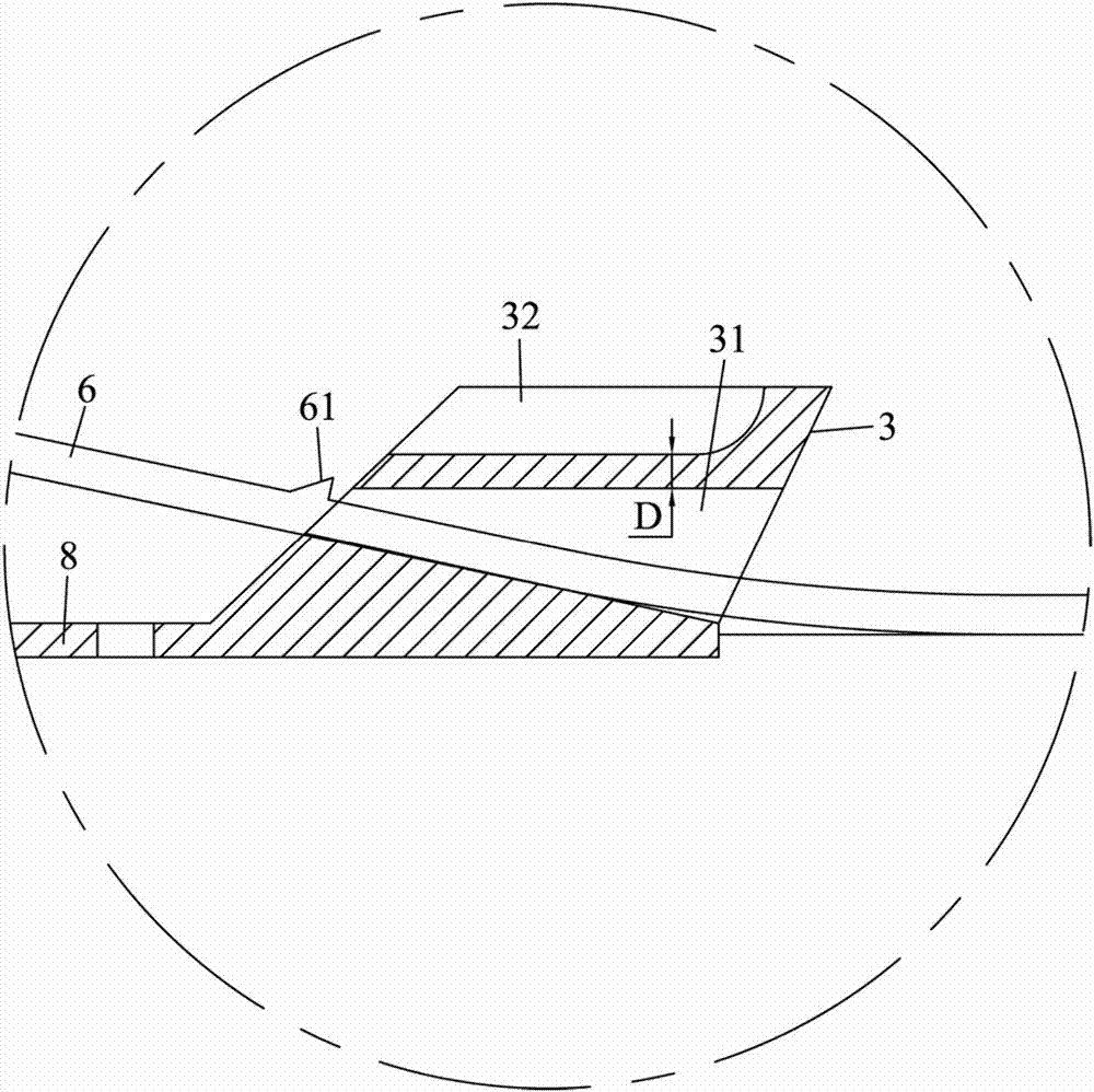
[0004] However, the connection structure of this stitched buckle still has shortcomings. The reason is that the guide groove is set to run through the lock buckle horizontally, and the thickness of the area corresponding to the guide groove at the top of the lock buckle is relatively large. Among them, the amplitude of upward elastic deformation is extremely small. Therefore, in order to make the cable tie pass through the guide groove smoothly, the height of the ratchet of the cable tie needs to be set smaller, which will reduce the clamping force of the ratchet and the pawl. , thereby reducing the tension between the two substrates and reducing the stitching effect
In addition, if the guide groove is opened horizontally, the bottom surface of the part where the cable tie passes through the guide groove will be in contact with the substrate. Therefore, before clamping the end of the cable tie, it is necessary to first connect the end of the cable tie sheet separation, which affects suturing efficiency

Method used


Image

  • Pull buckle type suture device
  • Pull buckle type suture device
  • Pull buckle type suture device

Examples


Embodiment Construction

[0012] The technical solutions in the embodiments of the present invention will be clearly and completely described below in conjunction with the accompanying drawings. Apparently, the described embodiments are only part of the embodiments of the present invention, not all of them. Based on the embodiments of the present invention, all other embodiments obtained by persons of ordinary skill in the art without creative efforts fall within the protection scope of the present invention.

[0013] It should be noted that if the embodiment of the present invention involves directional indications (such as up, down, left, right, front, back, top, bottom, inside, outside, vertical, horizontal, vertical, counterclockwise, clockwise, circumferential direction, radial direction, axial direction...), the directional indication is only used to explain the relative positional relationship, movement conditions, etc. When a change occurs, the directional indication changes accordingly.

[00...


PUM

PropertyMeasurementUnit
Thicknessaaaaaaaaaa

Abstract

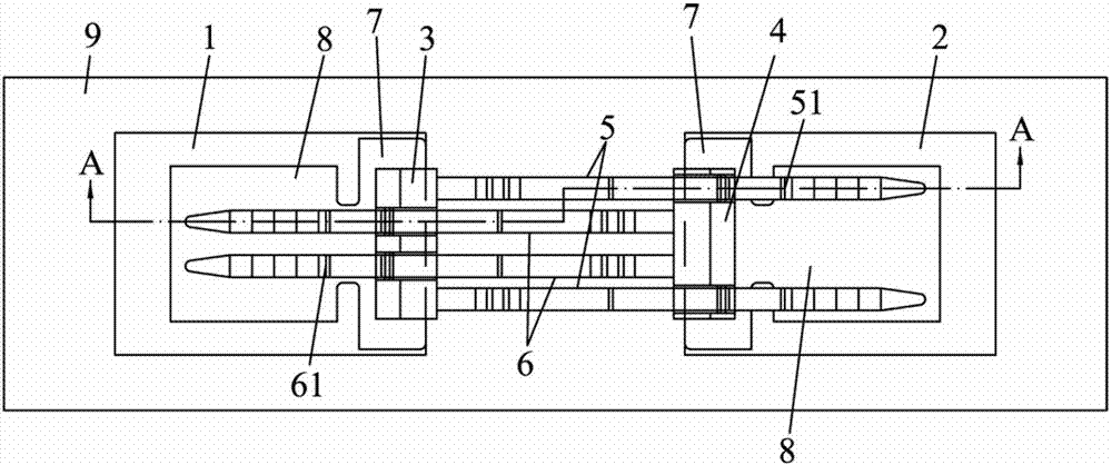
The invention discloses a pull buckle type suture device which comprises a first adhesive tape and a second adhesive tape adhered to the skin surfaces on two sides of a wound. The first adhesive tape and the second adhesive tape are fixedly provided with a first lock catch and a second lock catch which extending outward, a first bar and a second bar are fixedly arranged at the positions, corresponding to the first lock catch and the second lock catch, of the first adhesive tape and the second adhesive tape respectively, the first lock catch and the second lock catch are respectively provided with a first guide groove and a second guide groove for the first bar and the second bar to pass through, the zones, corresponding to the first guide groove and the second guide groove, of the tops of the first lock catch and the second lock catch are provided with a first avoiding groove and a second avoiding groove which respectively penetrate through the deviating end faces of the first guide groove and the second guide groove, the portions, penetrating through the second guide groove and the first guide groove, of the first bar and the second bar are provided with a first ratchet and a second ratchet extending outwards, and the first ratchet and the second ratchet respectively hooks the deviating end faces of the second lock catch and the first lock catch.

Description

technical field [0001] The invention relates to the technical field of skin surface wound suturing, in particular to a pull button type suturing device. Background technique [0002] Pull-button suturing device (also known as needle-free suturing device or needle-free pulling-button suturing device) is a surface suturing device that uses the skin's own tension to suture wounds on the skin surface non-invasively. It has the advantages of beautiful healing and other advantages, and it has a tendency to completely replace needle and thread suture wounds. [0003] For example, the Chinese Patent No. "ZL 2015207840700" discloses a connection structure of a suture pull button. During its use, two medical non-woven tapes are respectively pasted and fixed on the skin surface on both sides of the wound; The straps of the buckle pass through the guide grooves of the corresponding buckles respectively; then pull the straps of the two buckles in reverse to pull the skin closer to the c...

Claims


Application Information

Patent Timeline
IPC IPC(8): A61B17/08
CPCA61B17/085A61B2017/081A61B2017/086
Inventor 莫建雷谭振豪
Owner DONGGUAN MING LEI ELECTRONICS TECH
Learn More