
Riveting mechanism of automatic riveting machine

A technology of riveting mechanism and riveting machine, applied in multilayer circuit manufacturing, electrical components, printed circuit manufacturing, etc., can solve the problems of high scrap, difficult riveting processing, low work efficiency, etc., and achieve high production efficiency and high riveting quality , high work efficiency

Inactive Publication Date: 2017-07-21
庄召国
View PDF7 Cites 7 Cited by
  • Summary
  • Abstract
  • Description
  • Claims
  • Application Information

AI Technical Summary

Problems solved by technology

Although the circuit board is an indispensable and important part of the manufacture of electronic components, automobiles, household appliances, precision equipment, computer manufacturing, etc., its riveting process is a key and difficult process, because the circuit board is made of multiple thin inner sheets. Laminates are manufactured by superimposed riveting / riveting. At present, manual operation is used in the riveting / riveting section. First, pre-stacking is done by pre-stacking personnel. Superimposed riveting personnel can rivet 800-1000 sets of finished products every day, but the work efficiency is extremely low, and the scrapping of layers is relatively high. There is no good solution at present

Method used


Image

  • Riveting mechanism of automatic riveting machine
  • Riveting mechanism of automatic riveting machine
  • Riveting mechanism of automatic riveting machine

Examples


Embodiment Construction

[0025] The present invention will be further described below in conjunction with the accompanying drawings and specific preferred embodiments, but the protection scope of the present invention is not limited thereby.

[0026] Specific embodiments of the present invention will be described in detail below in conjunction with the accompanying drawings. It should be understood that the specific embodiments described here are only used to illustrate and explain the present invention, and are not intended to limit the present invention.

[0027] For the convenience of description, spatially relative terms may be used here, such as "on ...", "over ...", "on the surface of ...", "above", etc., to describe the The spatial positional relationship between one device or feature shown and other devices or features. It will be understood that the spatially relative terms are intended to encompass different orientations of the device in use or operation in addition to the orientation depic...


PUM


Abstract

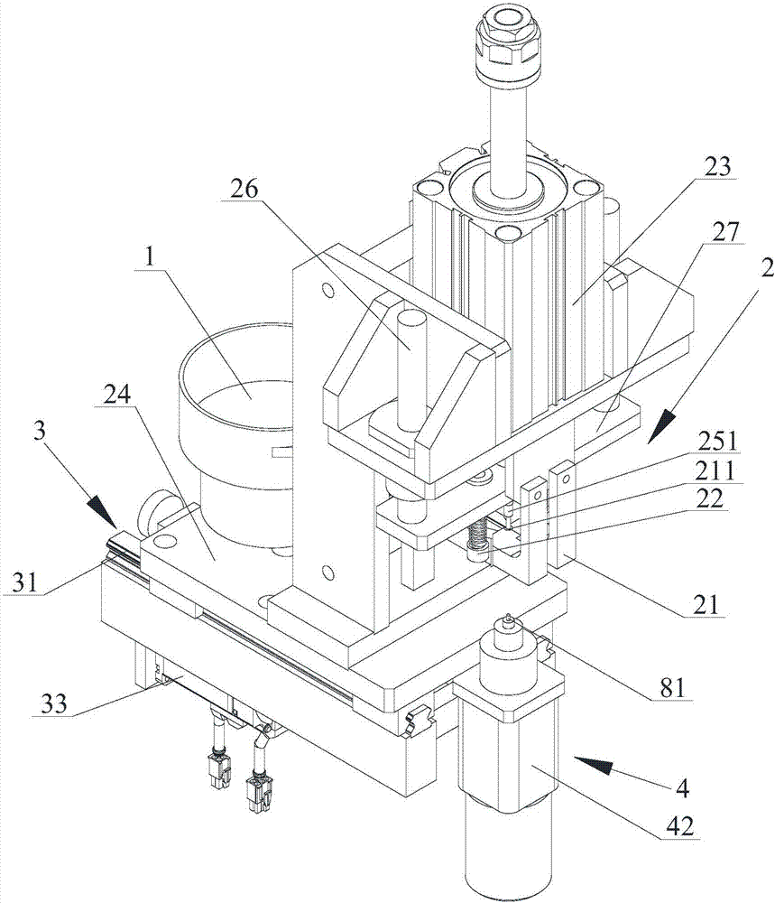
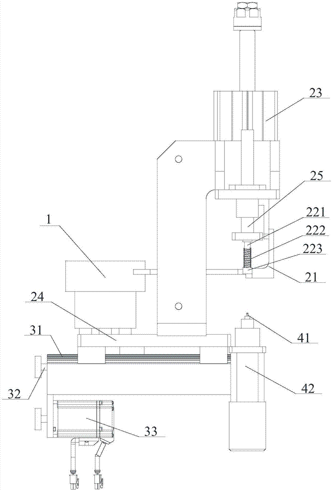
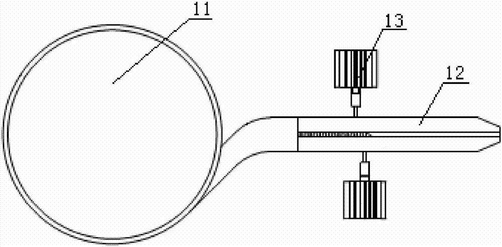
The invention discloses a riveting mechanism of an automatic riveting machine. The riveting mechanism comprises a vibrating plate, a riveting handpiece, a riveting driving device and an upper jacking and supporting device. The riveting handpiece comprises a material distribution dop, a prepressing device, a riveting pressure air cylinder, a mounting frame and a riveting pressure rod. The material distribution dop, the prepressing device, the riveting pressure air cylinder and the riveting pressure rod are mounted on the mounting frame. The mounting frame is mounted to the riveting driving device. The riveting handpiece and the upper jacking and supporting device move in the feeding direction of the riveting machine through the riveting driving device. The vibrating plate is connected with the material distribution dop. The riveting pressure air cylinder drives the riveting pressure rod and the prepressing device to go up and down. The riveting mechanism of the automatic riveting machine is high in riveting quality and production efficiency and low in cost, the defects that in the prior art, the manual labor amount is high, and the working efficiency and the reliability are low are overcome, and thus the low manual labor amount and high working efficiency and reliability are achieved.

Description

technical field [0001] The invention relates to the technical field of riveting machines, in particular to a riveting mechanism of an automatic riveting machine used for riveting circuit boards. Background technique [0002] As a common fixed connection method in mechanical processing, rivet connection has the advantages of low cost and high connection fastness. The existing rivet connection usually uses manual methods to place the rivet at a predetermined position and then uses special equipment for stamping and riveting. On the one hand, this method increases the labor intensity of the operator, affects work efficiency, and also has certain potential safety hazards in safe operation. [0003] The riveting machine, also known as the riveting machine, is a machine used to rivet the corresponding parts or plates that need to be riveted through the deformed rivets after the rivets are deformed by impact. The existing riveting machine needs to manually add unstamped rivet part...

Claims


Application Information

Patent Timeline
Patent Type & Authority Applications(China)
IPC IPC(8): B21J15/14B21J15/32H05K3/46
CPCB21J15/14B21J15/32H05K3/4611
Inventor 庄召国
Owner 庄召国
Learn More