Novel sewing machine rotating shuttle structure

A sewing machine, a new type of technology, applied in the direction of the sewing machine ring mechanism, sewing machine components, sewing equipment, etc., can solve the problems of high friction resistance between the shuttle frame guide rail and the shuttle bed, difficulty in controlling the amount of refueling, and affecting the sewing quality, so as to improve work efficiency. The effect of stability, avoiding unsmooth outlet, and improving service life

Active Publication Date: 2017-07-21
DONGYANG TAIJI PRECISION MFG
View PDF6 Cites 7 Cited by
  • Summary
  • Abstract
  • Description
  • Claims
  • Application Information

AI Technical Summary

Problems solved by technology

[0003] The present invention mainly provides a novel sewing machine rotary hook structure with small wear between the shuttle bed and the shuttle frame, fast heat dissipation, ensuring the normal operation of the rotary hook, and prolonging the service life of the sewing machine. The friction resistance ...

Method used


Image

  • Novel sewing machine rotating shuttle structure
  • Novel sewing machine rotating shuttle structure
  • Novel sewing machine rotating shuttle structure

Examples


Embodiment 1

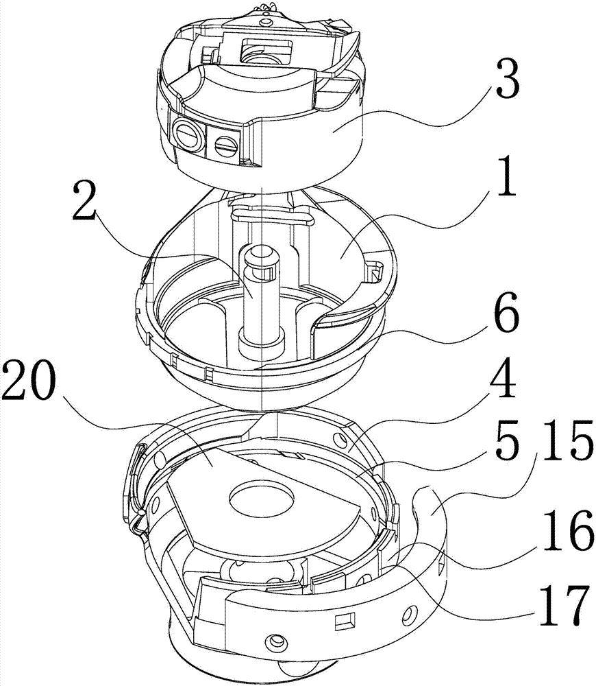
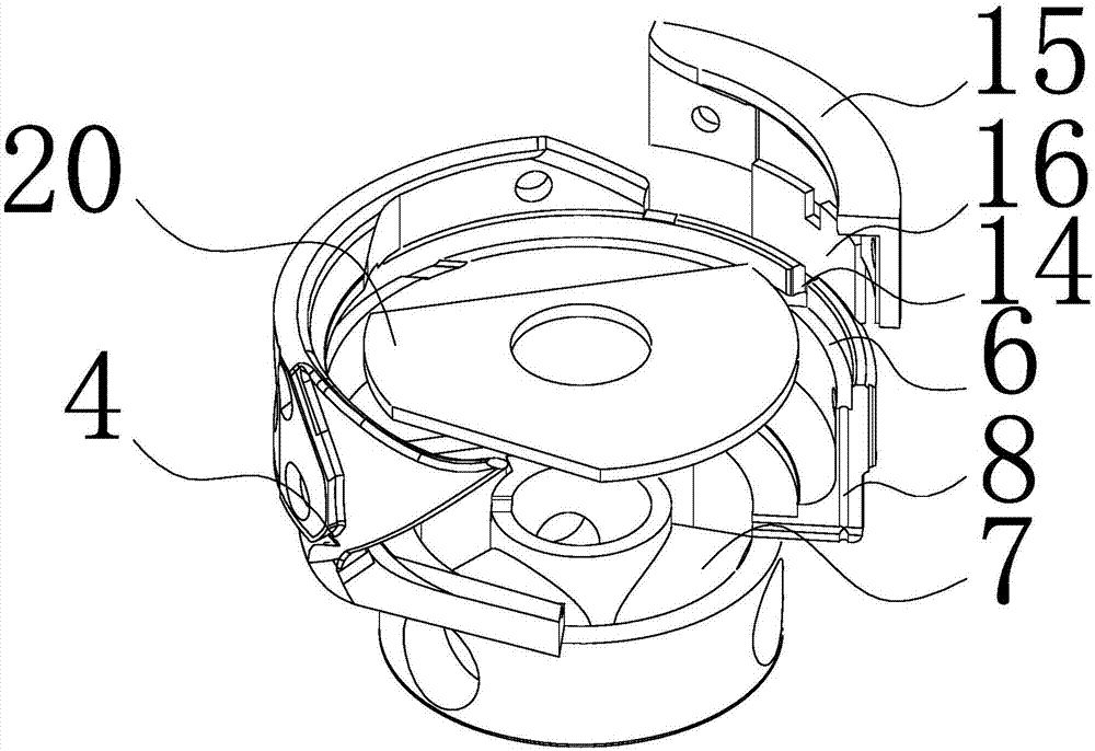
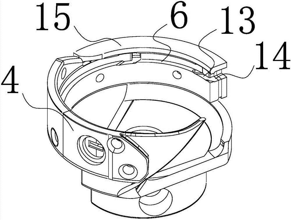
[0028] Such as figure 1 As shown, a novel sewing machine rotary hook structure of the present invention includes a bobbin frame 1 and a button cover fixed on the bobbin case 3 on the bobbin frame core 2 in the upper port of the bobbin frame 1, and the lower end of the bobbin frame 1 is matched with a cover. The shuttle bed 4 that can be rotated relative to the center of the shuttle frame core 2 is adorned, and the shuttle frame core 2 is a circular truncated shape with a small upper part and a larger lower part, such as Image 6 As shown, in the middle part of the bobbin case 3, there is a conical truncated bobbin case positioning hole 18 that matches each other, and the shuttle frame core 2 is inserted and fixed in the bobbin case positioning hole 18, as shown in FIG. figure 2 with image 3 As shown, on the outer ring surface of the shuttle bed 4, a moon ring 15 is interfitted with two left and right fixing screws, and a piece of wool felt 16 is sandwiched between the moon ...

Embodiment 2

[0030] Such as Figure 7 As shown, a passing steel wire 22 is embedded in the passing steel sheet limiting groove 12, the inner end of the passing steel wire 22 is fixed in the passing steel sheet limiting groove 12 by a rivet 23, and the outer end extends to the outside of the gap. All the other parts are identical to Example 1.


PUM


Abstract

The invention discloses a rotating shuttle structure, and provides a novel sewing machine rotating shuttle structure which has small abrasion between a shuttle race and a shuttle support, is fast in heat dissipation, guarantees that a rotating shuttle maintains normal work, and prolongs service life. The novel sewing machine rotating shuttle structure solves the technical problem in the prior art that friction resistance of a shuttle support guide rail and the shuttle race is big, the shuttle race guide rail and a rail table need to be lubricated and supplied with oil periodically, not only is the process complicated, but also the oil added amount is difficult to control, and the sewing quality is directly influenced. The novel sewing machine rotating shuttle structure comprises the shuttle support and a shuttle housing which is fixed on a shuttle support core at one end of the shuttle support, the other end of the shuttle support is covered with the shuttle race capable of rotating along the shuttle support core in a mutually matched mode, the inner annular surface of the shuttle race is provided with the rail table, the outer annular of the shuttle support is provided with the annular shuttle support guide rail, the shuttle support is supported on the rail table through the annular shuttle support guide rail, and keeps rotatable connection with the inner annular surface of the shuttle race, and the outer end face of the annular shuttle support guide rail is provided with multiple axial through holes connected to the rail table.

Description

technical field [0001] The invention relates to a rotary hook structure, in particular to a novel sewing machine rotary hook structure with less wear between the shuttle bed and the hook frame, fast heat dissipation and prolonged service life of the rotary hook. Background technique [0002] The rotary hook is an important part of the sewing machine. On the most commonly used lock stitch sewing machines in the clothing and shoe making industries, most of the rotary hooks are used. Enlarge the loop and guide the loop around the carriage to create a lockstitch. In the existing sewing machine rotary hook structure, the shuttle frame guide rail on the shuttle frame and the corresponding track platform on the shuttle bed are both sliding friction. When in use, because the shuttle bed is rotating at a high speed relative to the shuttle frame, in order to reduce the friction between the two friction, to ensure the normal operation of the rotary hook, it is necessary to regularly l...

Claims


Application Information

Patent Timeline
IPC IPC(8): D05B57/10D05B57/26D05B71/02
CPCD05B57/10D05B57/26D05B71/02
Inventor 黄仲新
Owner DONGYANG TAIJI PRECISION MFG
Why Eureka
Try Eureka