A pull-out drawer structure for a car

A pull-out, drawer technology, applied in passenger space, rack configuration, etc., can solve the problems of complex drawer structure, large space assembler restrictions, easy grease leakage, etc., to achieve long-term effective lubrication effect, easy to reduce weight Design, easy installation and maintenance effect

Active Publication Date: 2018-04-27
广州广汽优利得汽车内饰系统研发有限公司
View PDF8 Cites 0 Cited by
  • Summary
  • Abstract
  • Description
  • Claims
  • Application Information

AI Technical Summary

Problems solved by technology

However, this kind of drawer structure has the following disadvantages: 1. The structure is complicated, which is not easy to install and use; 2. It is heavy and not easy to realize portability; 3. The grease is easy to leak, which affects the service life of the drawer; 4. The cost is high.
The interior space of the car is small. During the assembly process, the space is very limited for the assemblers. The existing drawer structure is relatively complicated. During assembly and maintenance, it is extremely inconvenient for assembly and maintenance personnel to work; the weight of the car greatly affects For the performance of the car, the general car will concentrate its weight on the skeleton structure that ensures safety as much as possible, and the accessories such as drawers should be as light as possible to reduce the weight of the car and improve the performance of the car. However, the existing drawer structure is due to rollers and The heavy weight of the metal track is not conducive to the lightweight design of the car; the existing drawer structure is limited by the structure. service life; rollers and metal tracks need to be processed separately, increasing material and processing costs, thereby increasing production costs

Method used


Image

  • A pull-out drawer structure for a car
  • A pull-out drawer structure for a car
  • A pull-out drawer structure for a car

Examples


Embodiment Construction

[0021] In order to facilitate the understanding of those skilled in the art, the present invention will be further described in detail below in conjunction with the accompanying drawings and specific embodiments.

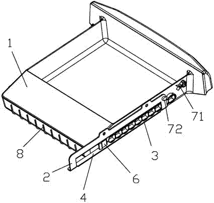
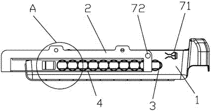
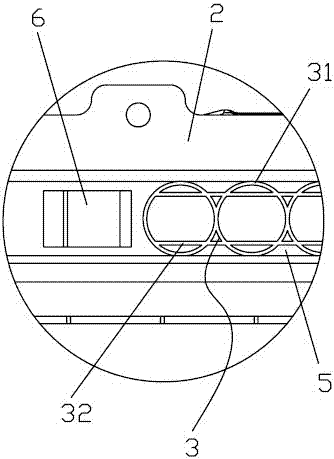
[0022] Such as figure 1 , figure 2 and image 3 As shown, a pull-out drawer structure for an automobile includes a drawer 1 and a support bar 2, and the support bar 2 is generally fixed on both sides of the drawer hole. Both sides of the drawer 1 are fixed with slide rails 3 , the support bar 2 is provided with a slide groove 4 matching with the slide rail 3 , and the slide rail 3 slides along the slide groove 4 . The slide rail 3 includes a plurality of annular protruding rings 31 connected in a row, and the outer ring edges between adjacent annular protruding rings 31 are connected to each other, and the annular protruding rings 31 are snapped into the chute 4, and the annular protruding rings 31 and the chute 4 For line contact, the contact area is small, the...


PUM


Abstract

The invention discloses a pull-out drawer structure of an automobile. The pull-out drawer structure comprises a drawer and support bars, wherein a slide rail is fixedly arranged on each of two sides of the drawer, and a sliding slot matched with the corresponding slide rail is formed in each support bar; each slide rail comprises a plurality of annular convex rings connected into a row, the outer edges of every two adjacent annular convex rings are connected, the annular convex rings are clamped in the sliding slots, and lubricating cavities for accommodating lubricating grease are formed between the annular convex rings and the corresponding sliding slot. According to the pull-out drawer structure of the automobile, the lubricating cavities for accommodating the lubricating grease are formed between the annular convex rings and the corresponding sliding slot, so that the lubricating grease is effectively locked, the lubricating effect can be effective for a long term, and the service life of the drawer is prolonged; the annular convex rings are matched with the sliding slots, so that the contact area is small, and the abrasion is lowered; in addition, the pull-out drawer is simple in structure, light in weight, and convenient in mounting, maintenance, and lightweight design.

Description

technical field [0001] The invention relates to the field of automobiles, in particular to an automobile pull-out drawer structure. Background technique [0002] In order to store some scattered items on the car, there are generally drawers in front of the front seats and rear seats. There are generally two types of drawers, one is flip type, and the other is pull type. Generally, according to the position And different types of space settings. The structure of the clamshell drawer is relatively simple, but it is inconvenient to clean; the structure of the pull-out drawer is relatively complicated, but the drawer can be completely pulled out, which is convenient for cleaning. [0003] The pull-out drawer of the car needs to realize the function of pushing and pulling. Generally, a mechanism with rollers is added between the two metal tracks to realize the function of pushing and pulling the drawer. This structure requires separately processed rollers and metal tracks to rea...

Claims


Application Information

Patent Timeline
Patent Type & Authority Patents(China)
IPC IPC(8): B60R7/04B60R7/08
CPCB60R7/04B60R7/08
Inventor 李兵梁福茂
Owner 广州广汽优利得汽车内饰系统研发有限公司
Why Eureka
Try Eureka