A hydraulic hammer control system

A technology of control system and hydraulic hammer, which is applied in the direction of fluid pressure actuation system components, fluid pressure actuation devices, servo motor components, etc., and can solve the problem of uneven wear of valve core and sleeve, complex oil circuit in separate installation, and poor oil flow. Small area and other problems, to improve hydraulic transmission efficiency, avoid uneven wear, and achieve the effect of large oil passage area

Active Publication Date: 2018-12-11
CHINA FORGING MACHINERY
View PDF4 Cites 0 Cited by
  • Summary
  • Abstract
  • Description
  • Claims
  • Application Information

AI Technical Summary

Problems solved by technology

[0005] The structure of this technology is complicated, the mass of the solid valve core is large, the oil passage area is small, the motion inertia of the valve core is large, and the sensitivity is low; the oil circuit of the separate installation is complicated, and the resistance along the way is large; the valve core and valve sleeve are prone to appear due to gravity when installed horizontally uneven wear
[0006] The existing technology generally uses cylinders or buffer pads to achieve return buffering, with complex structures and high failure rates

Method used


Image

  • A hydraulic hammer control system

Examples


Embodiment Construction

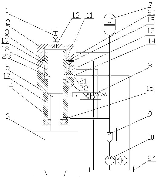
[0013] Such as figure 1 As shown, the hydraulic hammer control system includes a hydraulic cylinder 4, a hammer rod 5, a hammer head 6, a valve sleeve 2, and a cylindrical hydraulic valve core 3. The hydraulic cylinder 4 is a cylinder body 17 with an upper end opening, and the valve sleeve 2 is sealed and fixed on At the top of the cylinder block 17, the cylindrical hydraulic spool 3 is arranged in the valve sleeve 2 and the cylinder body 17. The cylindrical hydraulic spool 3 includes a cylindrical body 18 that penetrates up and down. The outer wall middle of the cylindrical body 18 is provided with an annular boss 19. A first step 20 is provided on the lower part of the inner side wall of the valve sleeve 2, and an annular groove 21 is formed between the lower step surface of the valve sleeve 2 and the top end of the hydraulic cylinder block 17, and the annular boss 19 fits in the annular groove 21. The inner side wall of the upper part of 17 is provided with a second step 22...


PUM


Abstract

The invention discloses a control system of a hydraulic hammer and belongs to the field of hydraulic machinery. The control system comprises a hydraulic cylinder, a hammer rod, a hammer head, a valve pocket and a cylinder hydraulic valve element. The valve pocket is fixed to the top end of a cylinder body in a sealing manner, the cylinder hydraulic valve element is arranged in the valve pocket and the cylinder body, an annular boss is arranged in the middle portion of the cylinder hydraulic valve, the annular boss is arranged between the part from a lower step face of the valve pocket to the lower end and the top end of the cylinder body of the hydraulic cylinder, a second step is arranged on the inner side wall of the upper part of the cylinder body, and the cylinder hydraulic valve element is arranged between the valve pocket and the second step of the cylinder body in a sliding fit manner. An inner end piston of the hammer rod is arranged in the cylinder hydraulic valve element and the cylinder body in a sliding fit manner. The side wall of the valve pocket is provided with a first oil opening, the side wall of the valve pocket is provided with a second oil opening and a third oil opening, the side wall of the cylinder body is provided with a fourth oil opening and a fifth oil opening, the center of the upper top end of the valve pocket is provided with a sixth oil opening, and the first oil opening, the second oil opening, the third oil opening, the fourth oil opening, the fifth oil opening and the sixth oil opening are connected with a hydraulic oil way system. The system is low in valve element weight, quick in responding, high in precision and high in hydraulic transmission efficiency.

Description

technical field [0001] The invention belongs to the field of hydraulic machinery, in particular to the technical field of hydraulic hammer control. Background technique [0002] There are two types of control methods for hydraulic hammers in the prior art: [0003] Several plug-in cone valves are used to jointly control the oil intake and discharge of the upper and lower chambers of the driving cylinder of the hydraulic hammer to realize the strike and return of the hammer head. The plug-in cone valves communicate with the upper and lower chambers of the hydraulic hammer driving cylinder through manifold channels or pipes. The technical structure is complicated, the control requirements of several cartridge valves are high, and the failure rate is high. [0004] The special hydraulic slide valve or cone valve is used to control the oil intake and discharge of the upper and lower chambers of the driving cylinder of the hydraulic hammer, so as to realize the strike and return...

Claims


Application Information

Patent Timeline
Patent Type & Authority Patents(China)
IPC IPC(8): F15B13/02F15B1/02F15B21/04F15B15/22
CPCF15B1/02F15B13/02F15B15/22F15B21/04
Inventor 张长龙王心云张为军王爱军陈太清
Owner CHINA FORGING MACHINERY
Why Eureka
Try Eureka