Load locking and adjusting improved constant force spring support hanging bracket

A constant force spring and improved technology, applied in the field of supports and hangers, can solve the problems of difficult concentricity, small output load adjustment range, fracture and other problems, and achieve the effects of large load adjustment range, convenient load adjustment and simple structure.

Active Publication Date: 2017-07-21
XIAN THERMAL POWER RES INST CO LTD
View PDF4 Cites 3 Cited by
  • Summary
  • Abstract
  • Description
  • Claims
  • Application Information

AI Technical Summary

Problems solved by technology

Its disadvantages are as follows: 1) The constant force spring hanger is suspended at high altitude and the load generally reaches several tons or even tens of tons. It is extremely difficult to adjust the centers of the four locking pin holes of the constant f

Method used


Image

  • Load locking and adjusting improved constant force spring support hanging bracket
  • Load locking and adjusting improved constant force spring support hanging bracket
  • Load locking and adjusting improved constant force spring support hanging bracket

Examples


Embodiment Construction

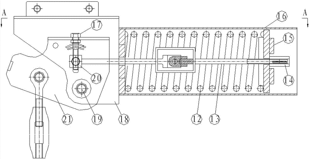
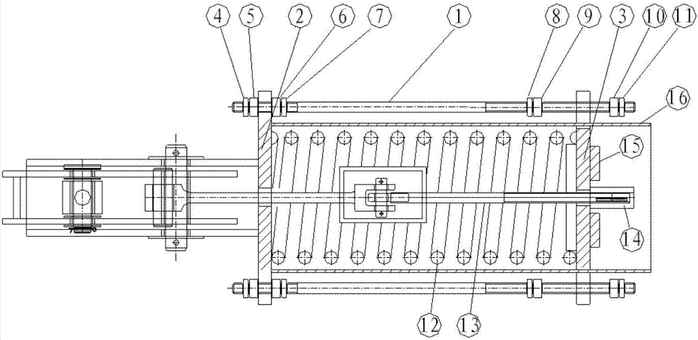
[0022] The present invention is described in further detail below in conjunction with accompanying drawing:

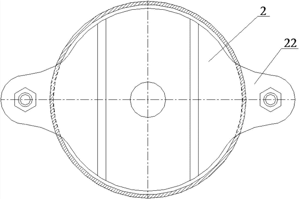
[0023] refer to figure 1 , the load locking and adjustment improved constant force spring support and hanger of the present invention includes a front end plate 2, a spring cover tube 16, an outer frame 18, a revolving frame 21, a pull rod 1, a main shaft 19, a tail end plate 3, a spring Pull rod 13, guide sleeve 20 and load adjustment nut 14; one side of the front end plate 2 is fixed on the end face of one end of the spring cover tube 16, the outer frame 18 is fixed on the other side of the front end plate 2, and the rotary frame 21 The end of the shaft is located in the outer frame 18, the main shaft 19 passes through the outer frame 18 and the revolving frame 21 to connect the outer frame 18 with the revolving frame 21, the tail end plate 3 is located in the other end of the spring cover tube 16, and the spring cover tube 16 A spring 12 is provided, and one end of...


PUM


Abstract

The invention discloses a load locking and adjusting improved constant force spring support hanging bracket. The load locking and adjusting improved constant force spring support hanging bracket comprises a front end plate, a spring cover barrel, an outer frame, a rotation frame, a pull rod, a spindle, a tail end plate, a spring pull rod, a guiding sleeve and a load adjusting nut. One side face of the front end plate is fixed to the end face of one end of the spring cover barrel, and the outer frame is fixed to the other side face of the front end plate. The end portion of the rotation frame is located in the outer frame. The spindle penetrates the outer frame and the rotation frame to connect the outer frame with the rotation frame. The tail end plate is located in the other end of the spring cover barrel. A spring is arranged in the spring cover barrel, one end of the spring pull rod is connected with the guiding sleeve, and the other end of the spring pull rod penetrates the outer frame and then penetrates the front end plate, the spring and the tail end plate to be connected with the load adjusting nut. The guiding sleeve and the rotation frame are connected through a load bolt. The support hanging bracket is convenient to lock, the load adjusting range is wide, and load adjustment is convenient.

Description

technical field [0001] The invention relates to a support and hanger, in particular to a load locking and adjustment improved constant force spring support and hanger. Background technique [0002] At present, the lever-type constant force spring support and hanger commonly used in the domestic electric power and petrochemical industries is manufactured according to the "Constant Force Spring Support and Hanger" JB / T 8130.1-1999 standard. After a period of operation, the outer frame plate and the rotary frame The four locking pin holes are generally not on the same axis. When performing pipeline hydraulic test, pipeline replacement and repair, and constant force spring hanger replacement, it is necessary to remove the four pins on the outer frame plate of the constant force spring hanger and the rotary frame in advance. Adjust the concentricity of the four locking pin holes, and then pass the locking pin through the above four locking pin holes to lock the constant force spr...

Claims


Application Information

Patent Timeline
IPC IPC(8): F16L3/00
CPCF16L3/00
Inventor 陈盛广王军民武彦飞吴晓俊田野安付立董雷邓玲惠秦沫邵若飞
Owner XIAN THERMAL POWER RES INST CO LTD
Why Eureka
Try Eureka