Supercharge Your Innovation With Domain-Expert AI Agents!

Acoustic lens system for loudspeakers

An acoustic lens and speaker technology, applied in the field of acoustic lens, can solve the problem that different characteristics of off-axis performance cannot be corrected electronically.

Active Publication Date: 2017-07-21
HARMAN INT IND INC
View PDF11 Cites 0 Cited by
  • Summary
  • Abstract
  • Description
  • Claims
  • Application Information

AI Technical Summary

Problems solved by technology

Often, different characteristics of off-axis performance cannot be corrected electronically

Method used


Image

  • Acoustic lens system for loudspeakers
  • Acoustic lens system for loudspeakers
  • Acoustic lens system for loudspeakers

Examples


Embodiment Construction

[0038] As required, detailed embodiments of the invention are disclosed herein; however, it is to be understood that the disclosed embodiments are merely examples of the invention which may be embodied in various alternative forms. The figures are not necessarily to scale; some features may be exaggerated or minimized to show details of particular components. Therefore, specific structural and functional details disclosed herein are not to be interpreted as limiting, but merely as a representative basis for teaching one skilled in the art to variously employ the present invention.

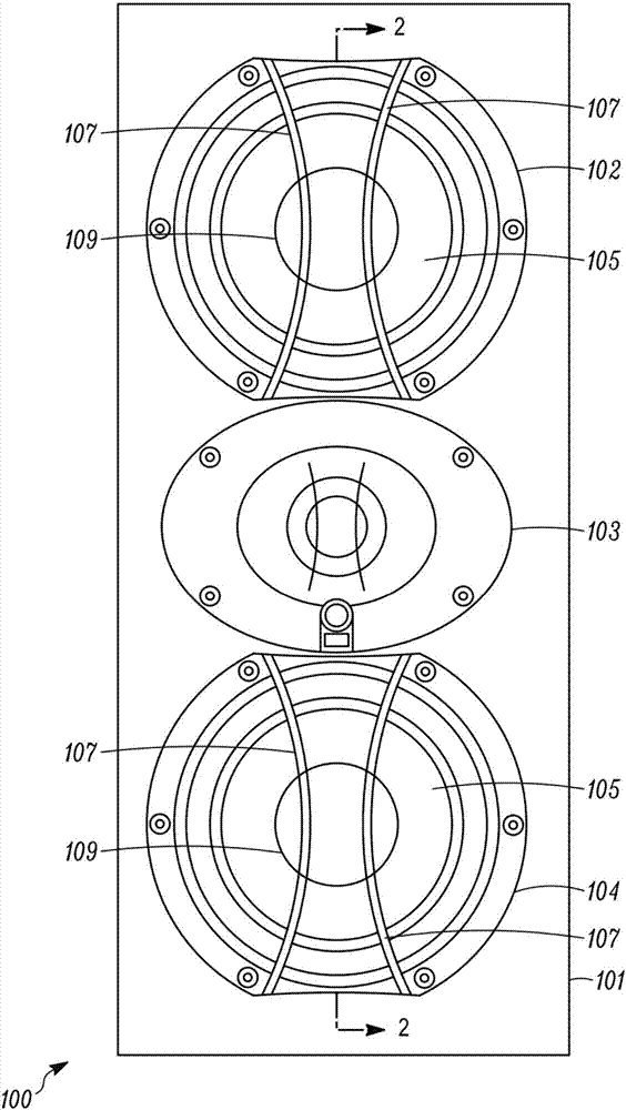
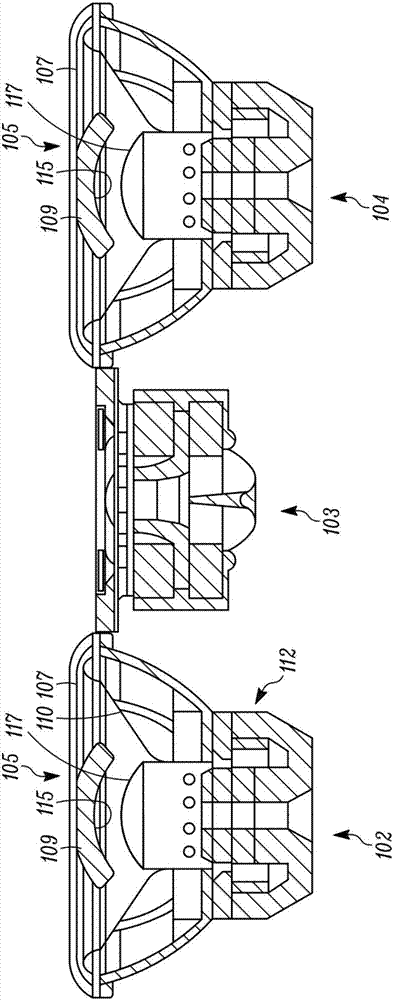
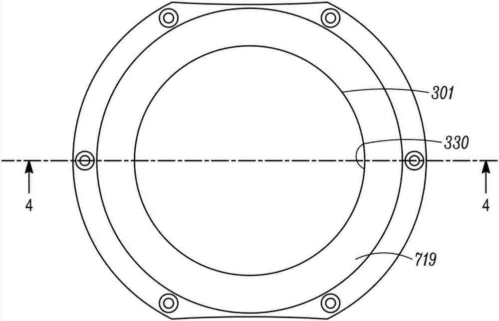
[0039] This specification describes lens assemblies for use in loudspeakers (eg, stand-alone speakers, automotive speakers, hall speakers, etc.). A lens assembly can be used to alter the sound quality of a speaker (eg, a mid-range transducer acting as a sound emitter). The lens assembly may include an acoustic lens positioned in front of or within an acoustic emitter (eg, a midrange transducer) to...


PUM


Abstract

An acoustic lens may improve the directional audio performance of a loudspeaker. Application of the improved directional audio performance to a sound system in a listening area may improve the performance of the audio system. The acoustic lens (or phase plug) may be acoustically opaque and partially fill the cavity formed by the loudspeaker cone. The acoustic lens may provide an improved frequency response and directivity. The improved loudspeaker may provide an improved listening location, for example, in a vehicle, a room or a concert hall.

Description

technical field [0001] Aspects disclosed herein relate generally to acoustic lenses, and more particularly, to speakers having an acoustic lens that can direct acoustic emissions from the speaker. Background technique [0002] The midrange in many speakers can suffer from timbre defects in the acoustic output at the end of the midrange bandwidth. The timbre defects may include peaks and valleys that may be caused by interference (constructive or destructive) of sound radiation from different regions of the diaphragm spatially originating. The peaks and valleys may also originate from Helmholtz cavity resonances formed by the conical diaphragm itself. Although in loudspeaker systems midrange transducer operation is usually band-limited at frequencies that limit low-pass filters to operate below frequencies at which peaks and valleys manifest themselves, such filters must be The tapered shape attenuates the midrange SPL by 6-24dB SPL / octave. As a result, mid-range timbre de...

Claims


Application Information

Patent Timeline
IPC IPC(8): H04R1/34H04R1/28H04R9/02H04R9/06
CPCH04R1/2873H04R1/345H04R9/02H04R9/06G10K11/30H04R2201/34H04R1/023
Inventor T.格拉德温M.格雷泽J.戈卡维
Owner HARMAN INT IND INC
Features
  • R&D
  • Intellectual Property
  • Life Sciences
  • Materials
  • Tech Scout
  • Unparalleled Data Quality
  • Higher Quality Content
  • 60% Fewer Hallucinations
Learn More