
Method of identifying a wireless communication channel in a sound system

a wireless communication and sound system technology, applied in the field of sound systems, can solve the problem of time-consuming in finding the appropriate channel, and achieve the effect of speeding up the search

Active Publication Date: 2012-11-29
OTICON
View PDF3 Cites 84 Cited by
  • Summary
  • Abstract
  • Description
  • Claims
  • Application Information

AI Technical Summary

Benefits of technology

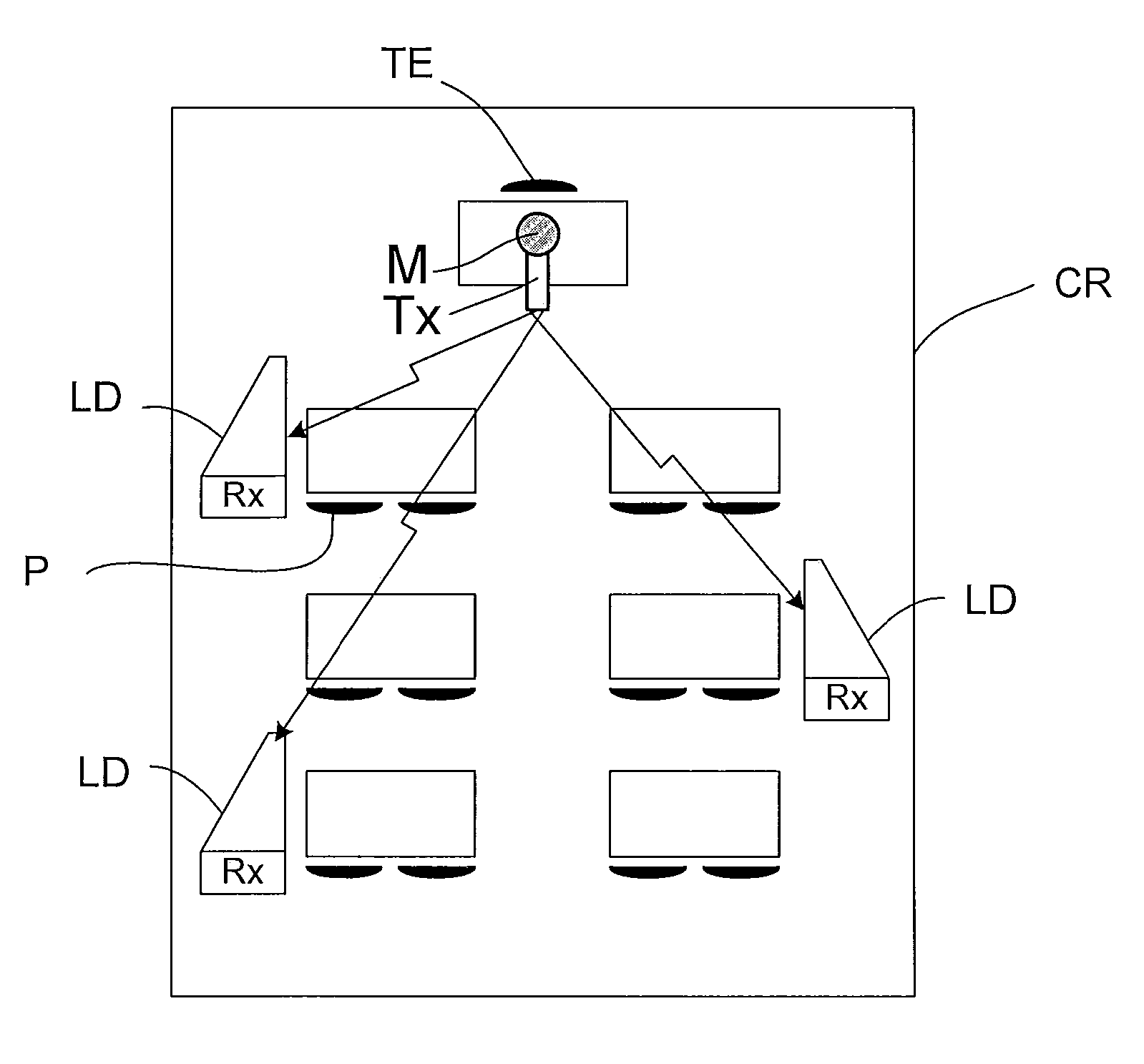
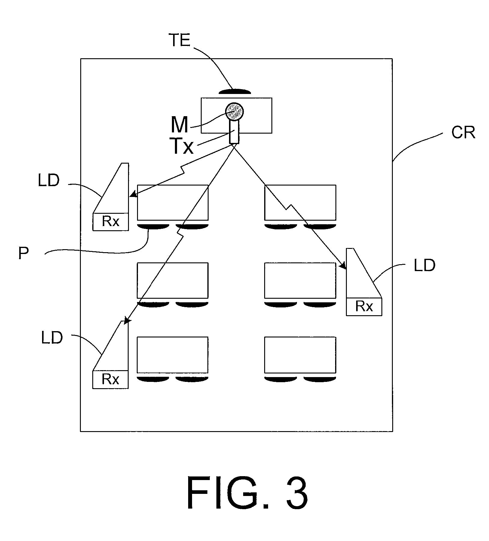
[0037]An advantage of the method is that it provides a relatively simple scheme for selecting an appropriate communication channel. A further advantage is that it provides a channel selection scheme that is suitable for a unidirectional (e.g. broadcasting) communication link (where no return channel is available for negotiating an appropriate channel). An advantage of an embodiment is that it may utilize existing components (wireless receiver, microphone) of a listening system to provide channel selection.
[0103]In an embodiment, a sound system comprises a multitude of listening devices as described above, in the detailed description of ‘mode(s) for carrying out the invention’ and in the claims. In an embodiment, the sound system comprises one or more sets of binaural listening device systems, e.g. binaural hearing aid systems, each binaural listening device system comprising first and second listening devices (e.g. hearing instruments) adapted for being located at or in left and right ears of a user. In a preferred embodiment, each listening device of the binaural system comprises transceiver circuitry allowing an interaural wireless link to be established whereby an exchange of signals between the two devices is enabled. In an embodiment, the two listening devices are adapted to allow the exchange of status and / or control signals, e.g. including a channel selection signal. In an embodiment, the two listening devices are, additionally or alternatively, adapted to allow the exchange of audio signals (or at least a part of the frequency range of the audio signals) between them. In an embodiment, the system is adapted to provide that the channel selection procedure is performed (only) in one of the two listening devices of a binaural system. In an embodiment, the binaural system is adapted to provide that a control signal (channel selection signal) for indicating a transmission channel identified in a listening device of the binaural system is transmitted to the other listening device of the system via the interaural wireless link. In an embodiment, the system is adapted to provide that the channel selection procedure is performed in both listening devices of a binaural system. In an embodiment, the system is adapted to provide that a channel is selected in a given listening device only if the same channel is identified as the correct channel in the other (contralateral) listening device of a binaural system. In an embodiment, the system is adapted to provide that the channel selection procedure is performed according to a list of predefined possible transmission channels. In an embodiment, the system is adapted to provide that the channel selection procedure is performed in the two listening devices of a binaural system according to a list of predefined possible transmission channels, so that the two listening devices start from opposite ends of the list. Preferably, the first listening device to identify a correct (active) channel having a signal correlating with the microphone signal of the device selects this channel as a receiving channel, and transmits a control signal (channel selection signal) to the other listening device of the system, thereby selecting this channel as a receiving channel in the other listening device as well, and further terminating the search for an appropriate transmission signal in that device. This has the advantage of speeding up the search for an appropriate (receiving) channel.

Problems solved by technology

One disadvantage of the above approach is that, it may be time consuming to find the appropriate channel.

Method used


Image

  • Method of identifying a wireless communication channel in a sound system
  • Method of identifying a wireless communication channel in a sound system
  • Method of identifying a wireless communication channel in a sound system

Examples


Embodiment Construction

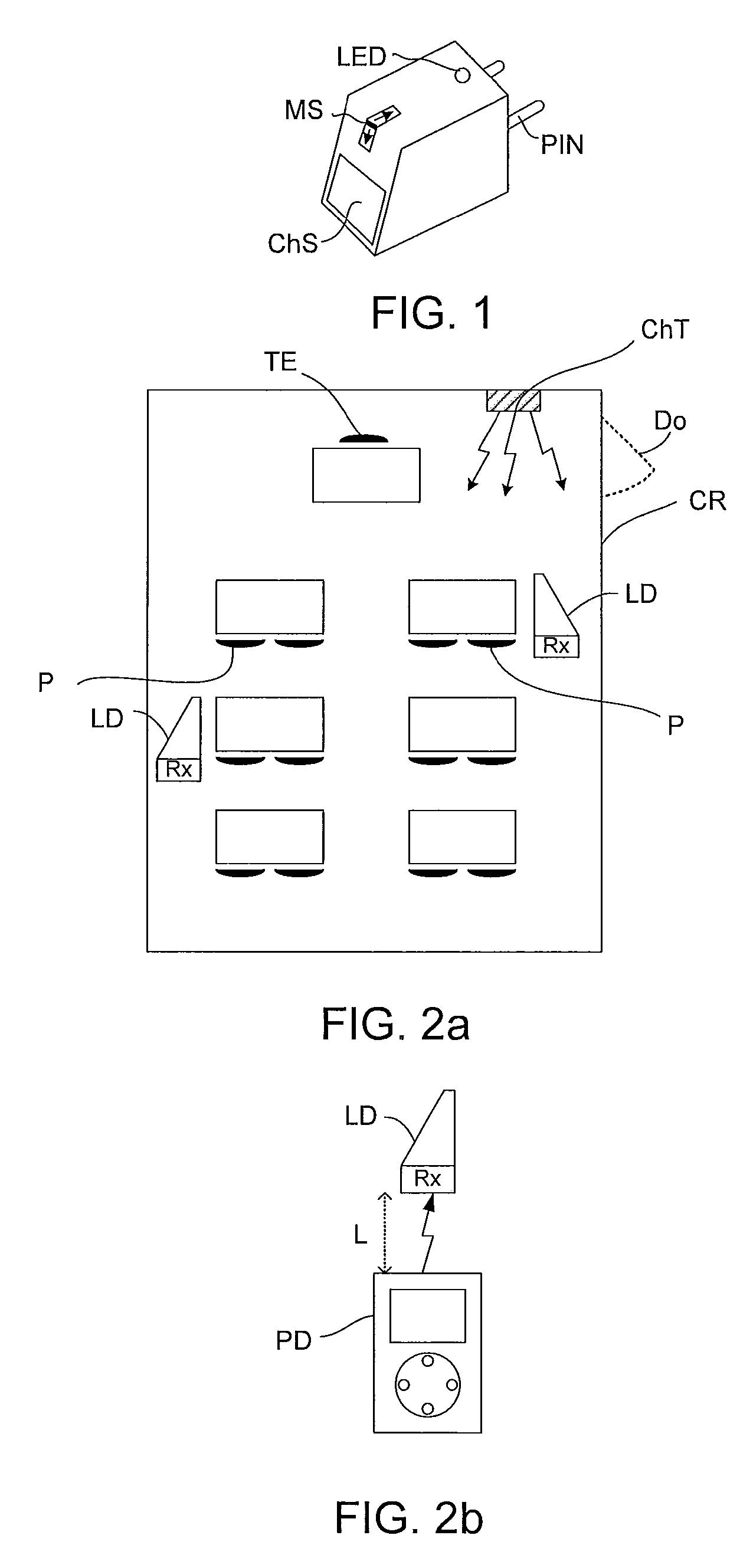
[0123]FIG. 1 shows a sketch of a prior art wireless FM receiver device, here similar to the Oticon R2, comprising push button control of the communication channel. The device in FIG. 1 represents in the framework of the present application a radio part. In practice, the part is often also termed an ‘FM-shoe’ or an ‘FM-pin’, referring to the fact that the device comprises a wireless receiver adapted for reception of an FM-signal and that it is electrically connectable to another hearing aid part via an electric connector (cf. PIN in FIG. 1), the other part typically comprising the normal functions of a hearing aid (input and output transducers and signal processing, etc.). The device in FIG. 1 comprises a three-position switch (MS) for selecting an appropriate mode of the device, a push button (ChS) for selecting another channel, and a light indicator (LED).

[0124]FIG. 2 shows a prior art scheme for communication channel control in listening devices using a wall-mounted transmitter (F...


PUM


Abstract

A method of identifies an appropriate wireless communication channel in an audio receiving device, that comprises 1) a wireless receiver receiving an audio signal on a particular transmission channel selected among a predefined number of possible transmission channels, and 2) a microphone for picking up a sound in the environment of the audio receiving device. The method comprises a) selecting a channel as the receiving channel among a predefined number of possible transmission channels; b) analyzing the received signal received and the signal picked up by the microphone; c) determining whether a predefined criterion concerning the degree of similarity of the received signal and the signal picked up by the microphone is fulfilled; d) KEEPING the channel as the receiving channel, if the predefined criterion is fulfilled; and e) CHANGING the receiving channel to another channel if the predefined criterion is NOT fulfilled.

Description

TECHNICAL FIELD[0001]The present application relates to a sound system, e.g. a sound amplification system comprising wireless communication between various parts of the system. The disclosure relates specifically to an audio receiving device for receiving a wireless signal comprising audio, and to a method of identifying an appropriate wireless communication channel in an audio receiving device. The application furthermore relates to a listening device and to a sound system comprising an audio receiving device.[0002]The application further relates to a data processing system comprising a processor and program code means for causing the processor to perform at least some of the steps of the method and to a computer readable medium storing the program code means.[0003]The disclosure may e.g. be useful in applications comprising simultaneous acoustic propagation and wireless transmission of an audio signal to an audio receiving device, e.g. in a sound amplification system, e.g. classro...

Claims


Application Information

Patent Timeline
Patent Type & Authority Applications(United States)
IPC IPC(8): H04B7/00
CPCH04R25/43H04R25/552H04R25/554H04R25/558H04R25/407H04R2225/61G09B5/04G09B21/006H04R27/02H04R2225/51G10L25/78H04R27/00H04R29/007H04R29/008H04R2420/07
Inventor KLEMMENSEN, BJARNE
Owner OTICON
Learn More