Wave absorbing body and wave absorbing module

A technology of a wave absorbing body and a body, which is applied in the field of wave absorbing structures, can solve the problems of the reduced wave absorbing effect of the wave absorbing body and the low limit of electromagnetic wave resistance, and achieve the effect of high power limit and improved power limit.

Pending Publication Date: 2017-07-21
深圳唯创微波技术有限公司
View PDF9 Cites 1 Cited by
  • Summary
  • Abstract
  • Description
  • Claims
  • Application Information

AI Technical Summary

Problems solved by technology

[0003] To sum up, the object of the present invention is to provide a wave absorber, which aims to solve the problem that the overall absorbing effect of the existing wave absorber is reduced because the internal heat cannot be removed in time during the wave absorbing process. And the problem of its low power limit of electromagnetic wave resistance

Method used


Image

  • Wave absorbing body and wave absorbing module
  • Wave absorbing body and wave absorbing module
  • Wave absorbing body and wave absorbing module

Examples


Embodiment 1

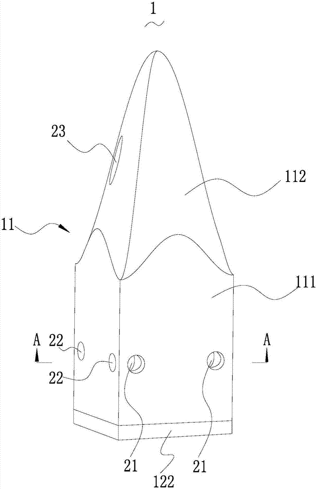
[0037] Please refer to image 3 , Figure 5 with Figure 6 , The absorber 1 provided by the embodiment of the present invention includes a main body 11 and a heat conduction component 12, and the heat conduction component 12 is used to conduct the internal heat of the main body 11 to the outside. The main body 11 is a rigid foam main body 11, and the heat conduction assembly 12 penetrates into the main body 11 from the bottom end of the main body 11 (here, the bottom end of the main body 11 is defined as the end for placing on the desktop; The opposite part is the top part). When the internal temperature of the main body 11 increases due to the absorption of incident electromagnetic waves, the heat conduction component 12 can conduct the heat inside the main body 11 to the outside of the main body 11 .

[0038] The absorber 1 provided in the embodiment of the present invention is provided with a heat conducting component 12 . When the main body 11 absorbs the incident elec...

Embodiment 2

[0055] Please refer to Figure 11 , the difference from the above-mentioned embodiment is that the heat conduction assembly 12 includes an inlet pipe 123, an outlet pipe 124 communicated with the inlet pipe 123, and a pump body (not shown in the figure), and the inlet pipe 123 and the outlet pipe 124 are formed by the base part The bottom end of 111 penetrates and is inserted into the wave-absorbing part 112 , the cooling water is pumped into the water inlet pipe 123 through the pump body, and then flows out through the water outlet pipe 124 . In this way, the heat inside the base part 111 and the wave absorbing part 112 is conducted to the outside by means of water cooling.

[0056] Not shown in the figure, the embodiment of the present invention also provides a wave absorbing module, including the above wave absorber 1 . Each absorber 1 is distributed in an array, the base parts 111 of adjacent absorbers 1 are spliced ​​together, the first heat conduction channels 21 of two...


PUM


Abstract

The invention relates to the technical field of wave absorbing structures, and provides a wave absorbing body. The wave absorbing body comprises a body and a thermal conduction module, wherein the thermal conduction module is used for conducting the internal heat of the body to the outside. The body is a hard foam body, and the thermal conduction module stretches into the body from the bottom end part of the body. When the body absorbs an incident electromagnetic wave and the internal temperature of the body is caused to rise, the thermal conduction module can enable the internal heat in the body to be conducted to the exterior of the body. Therefore, the wave absorbing body enables the heat generated in the wave absorbing process of the body to be conducted by the thermal conduction module to the outside under the condition that the material of the body is not changed, so the wave absorbing body increases the power limit for resisting electromagnetic waves of the body on the condition that the original wave absorbing performance of the body is not reduced. In other words, the body can be used for electromagnetic waves with higher power.

Description

technical field [0001] The invention relates to the technical field of wave absorbing structures, in particular to a wave absorbing body and a wave absorbing module with the wave absorbing body. Background technique [0002] During high-power antenna measurements, the absorber will absorb the electromagnetic energy of the incident electromagnetic wave and convert it into heat. At present, the wave-absorbing structure is made of rigid foam material. As we all know, the wave-absorbing structure of foam material is a poor conductor of heat, and its thermal conductivity is only one tenth of that of ordinary plastic, and one hundredth or even of that of a good heat conductor. lower. When the absorbing material absorbs the incident electromagnetic wave, a large amount of heat is generated in the absorbing structure, and the heat on its surface can be convectively exchanged with the external air, while the internal heat is difficult to quickly dissipate through heat conduction and...

Claims


Application Information

Patent Timeline
Patent Type & Authority Applications(China)
IPC IPC(8): H05K7/20H01Q17/00
CPCH01Q17/00H05K7/2039
Inventor 刘列龚攀君于伟漆一宏
Owner 深圳唯创微波技术有限公司
Why Eureka
Try Eureka